Rotary kiln valve set platform CO detection apparatus and method

A detection device and rotary kiln technology, which is applied in the field of rotary kiln, can solve the problems of inability to judge the location of air leakage point and small monitoring range, and achieve the effect of reducing the scope of maintenance, reducing labor intensity and improving safety factor

Active Publication Date: 2016-10-26
ZHONGYE-CHANGTIAN INT ENG CO LTD
View PDF10 Cites 6 Cited by
  • Summary
  • Abstract
  • Description
  • Claims
  • Application Information

AI Technical Summary

Problems solved by technology

[0010] The purpose of the present invention is to provide a dynamic patrol type rotary kiln valve group platform CO detection device and detection method to solve the

Method used


Image

  • Rotary kiln valve set platform CO detection apparatus and method
  • Rotary kiln valve set platform CO detection apparatus and method
  • Rotary kiln valve set platform CO detection apparatus and method

Examples


Embodiment 1

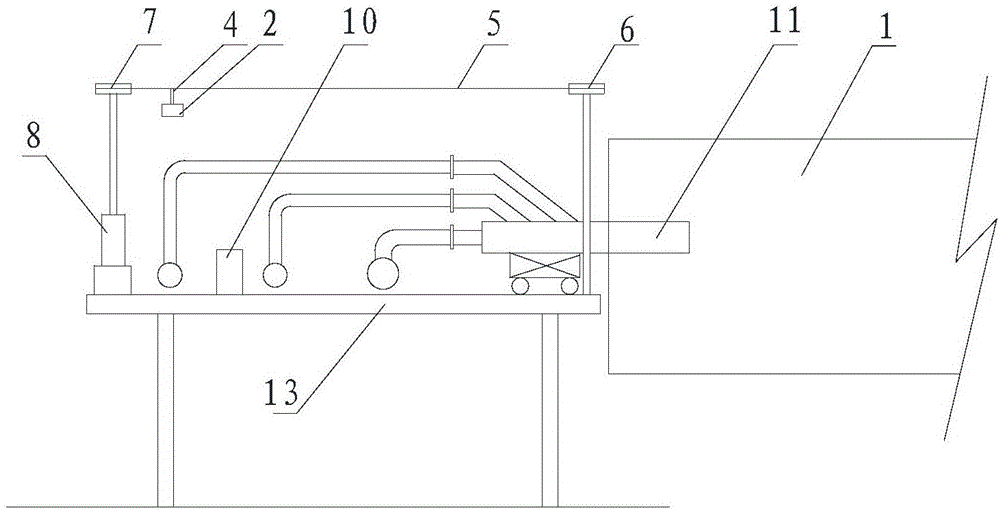
[0047] For the CO detection device of the rotary kiln valve group platform in the first embodiment, please refer to image 3 , the closed circuit is located above the valve group platform 13 . The CO detector 2 is installed under the closed circuit, and the closed circuit drives the CO detector to move cyclically on the valve group platform 13 . Obviously, since the CO detector 2 moves along with the closed circuit, the CO detector 2 is a CO wireless detector, and the cables and cable bushings can be omitted, which not only saves space on the furnace top, but also reduces the possibility of operating problems. Hazard of tripping over cable glands and falling.

[0048] When the CO wireless detector is hung under the closed circuit, the CO wireless detector is closer to the valve group platform 13, so that the CO concentration at each position on the valve group platform 13 can be accurately monitored. Among them, preferably but not necessarily image 3 As shown in the figure...

Embodiment 2

[0060] The difference from the first embodiment is that the closed route of the second embodiment is triangular, so that the closed route drives the CO wireless detector to move circularly along the triangular loop, please refer to Figure 6 .

[0061] On this basis, the number of driving sprocket 7 in the second embodiment is one, and the number of driven sprocket 6 is two, and they are distributed in three corner positions.

[0062] In the above embodiments, the locator can be in the form of a limit switch 9 . Specifically, when the CO wireless detector passes the set position, the limit switch 9 is turned on, and the limit switch 9 sends a trigger signal to the controller, and the controller receives the trigger signal The timing of the signal and the speed at which the closed line moves calculate the real-time position of the CO wireless detector.

[0063] see further Figure 6 , when the CO detector 2 passes above the limit switch 9, the CO detector 2 presses the limit...


PUM


Abstract

The invention relates to the technical field of rotary kilns and provides a rotary kiln valve set platform CO detection apparatus and method, wherein a CO wireless detector of the rotary kiln valve set platform CO detection apparatus is mounted on a closed line, moves with the same and transmits measured CO concentration value to a controller; a positioner is used for tracking a position of the CO wireless detector and transmitting positional information to the controller; the controller establishes a mapping relation between the CO concentration value and the positional information. In the scheme, the CO wireless detector cycles on a valve set platform and has a monitoring range covering the whole valve set platform, leakage of a valve at any position on the valve set platform will be captured by the CO detector, and thus, production safety coefficient is greatly improved. In addition, the scheme may analyze a positional range of leakage points according to CO concentration values of the positions, thereby greatly narrowing a maintenance range for an operator, saving time, improving work efficiency and reducing labor intensity.

Description

technical field [0001] The invention relates to the technical field of rotary kiln, in particular to a CO detection device and detection method for a rotary kiln valve group platform, more specifically a dynamic patrol type rotary kiln valve group platform CO detection device and detection method. Background technique [0002] Rotary kiln, also known as rotary calcining kiln, is a large-scale equipment in the core industry, which is widely used in building materials, metallurgy, chemical industry, environmental protection and other production industries. Its function is to use rotation and internal high temperature to calcine the materials in the kiln to form finished ore. Rotary kiln can be divided into cement kiln, metallurgical chemical kiln and lime kiln according to different materials. Cement kilns are mainly used for calcining cement clinker, which can be divided into two categories: dry production cement kiln and wet production cement kiln. Metallurgical and chemic...

Claims


Application Information

Patent Timeline
IPC IPC(8): G01N33/00G08C17/02
CPCG01N33/004G08C17/02
Inventor 周浩宇
Owner ZHONGYE-CHANGTIAN INT ENG CO LTD
Why Eureka
Try Eureka