
Lens dispensing and pressure maintaining equipment and method

A dispensing and lens technology, used in instruments, installations, optics, etc., can solve the problems of adhesive bonding performance failure, product structural stability reduction, failure and other problems, achieve high positioning accuracy, avoid structural defects, guarantee effect of time

Active Publication Date: 2018-11-30
GOERTEK OPTICAL TECH CO LTD
View PDF4 Cites 0 Cited by
  • Summary
  • Abstract
  • Description
  • Claims
  • Application Information

AI Technical Summary

Problems solved by technology

However, the reliability of manually assembling the lens is relatively low. Due to the characteristics of the adhesive itself, it must be required to install the lens within a certain period of time and carry out a certain period of pressure holding, otherwise it will affect the structural reliability of the product. It is difficult to guarantee the time and timely rate of work
The main disadvantages are as follows: 1. After dispensing, if the personnel cannot install the lens in time, the adhesive performance of the adhesive will gradually fail, thereby affecting the quality of the product; 2. After the lens is installed manually, if the lens is not maintained in time pressure, the adhesive gradually fails, and the stability of the product structure decreases; 3. Due to the high requirements for the installation accuracy of the lens, it is difficult to guarantee the positioning accuracy by manual work; cannot be guaranteed to be precise

Method used


Image

  • Lens dispensing and pressure maintaining equipment and method
  • Lens dispensing and pressure maintaining equipment and method
  • Lens dispensing and pressure maintaining equipment and method

Examples


Embodiment Construction

[0029] Various exemplary embodiments of the present invention will now be described in detail with reference to the accompanying drawings. It should be noted that the relative arrangements of components and steps, numerical expressions and numerical values ​​set forth in these embodiments do not limit the scope of the present invention unless specifically stated otherwise.

[0030] The following description of at least one exemplary embodiment is merely illustrative in nature and in no way taken as limiting the invention, its application or uses.

[0031] Techniques, methods and devices known to those of ordinary skill in the relevant art may not be discussed in detail, but where appropriate, such techniques, methods and devices should be considered part of the description.

[0032] In all examples shown and discussed herein, any specific values ​​should be construed as exemplary only, and not as limitations. Therefore, other instances of the exemplary embodiment may have dif...


PUM


Abstract

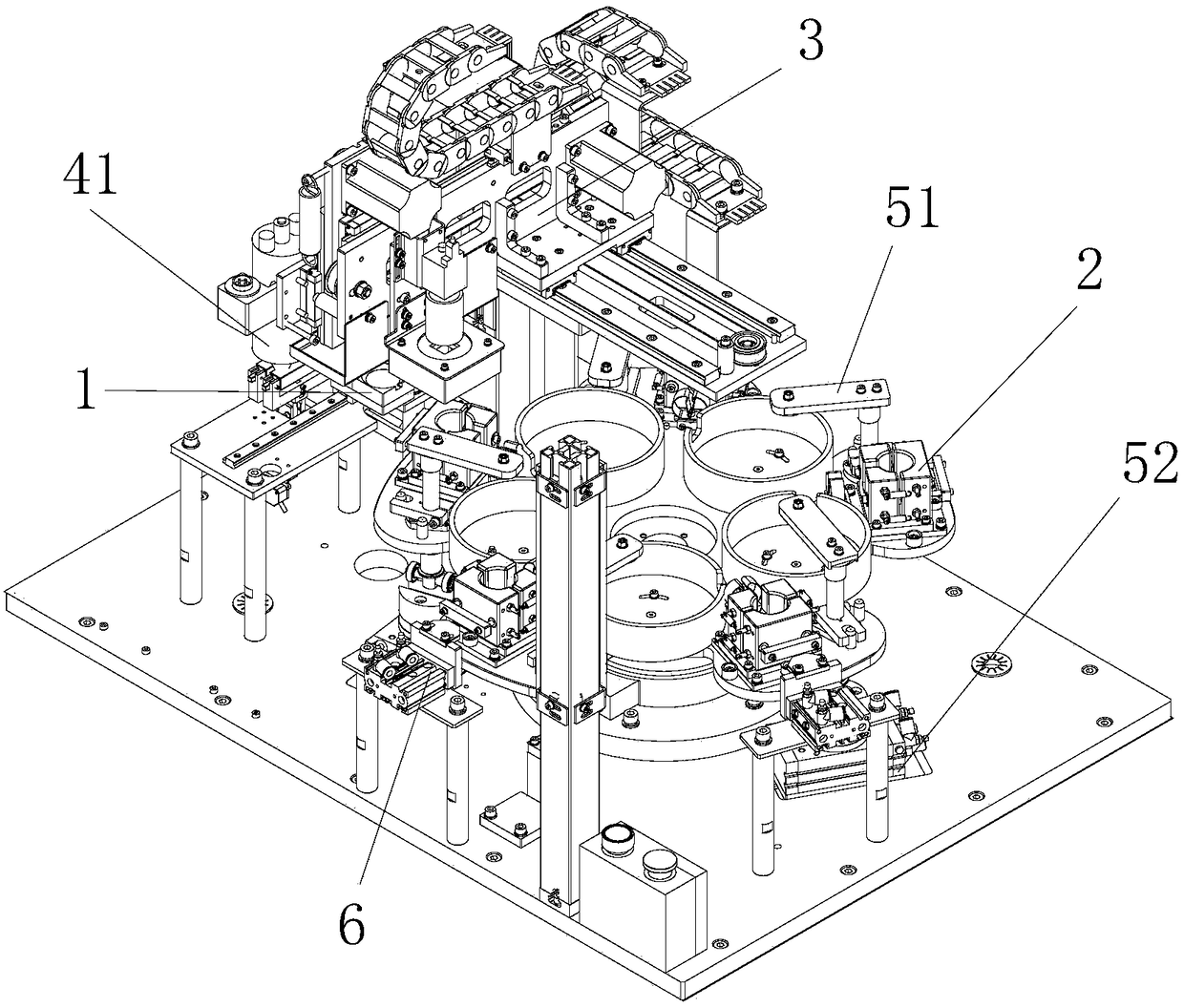
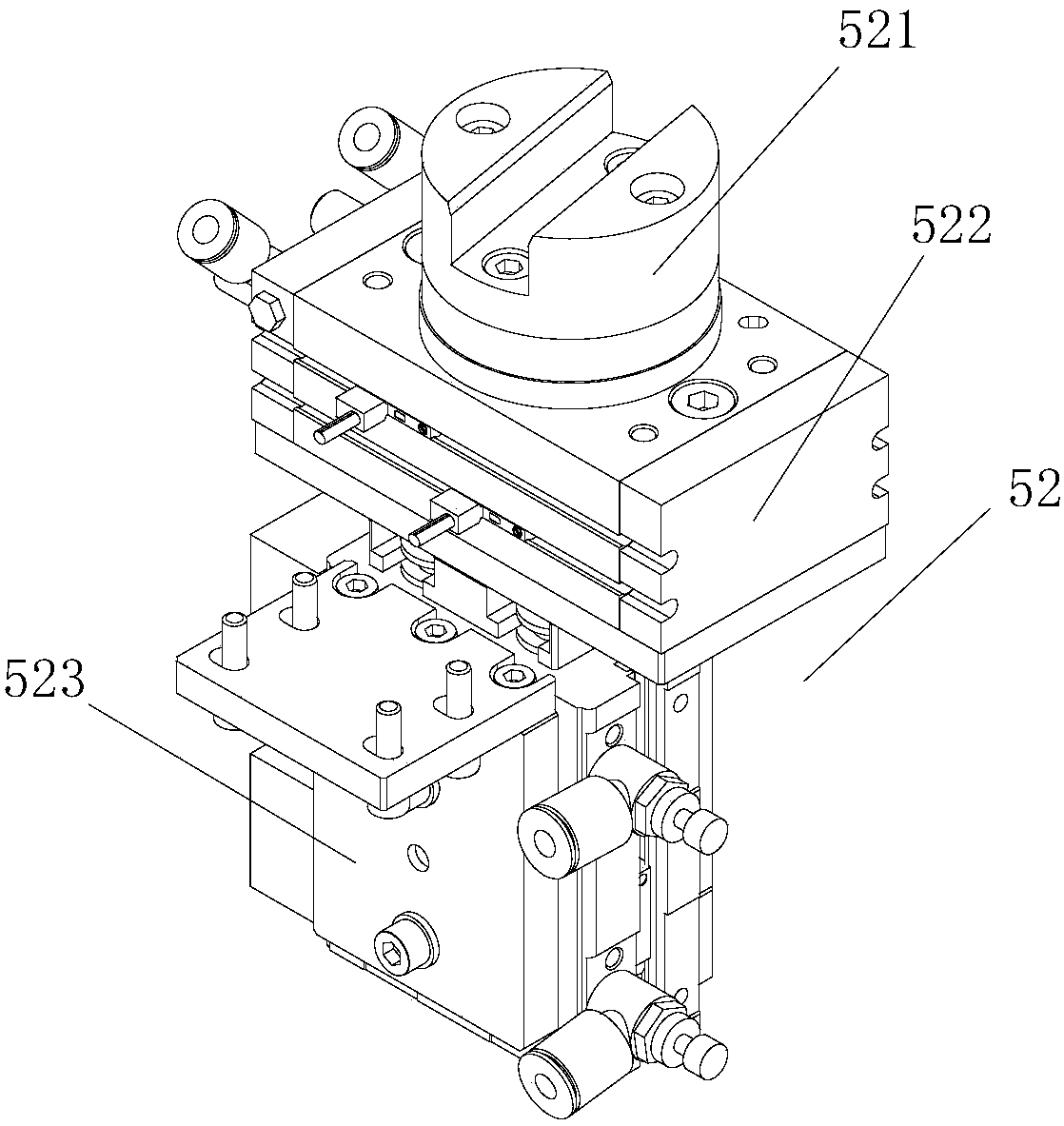
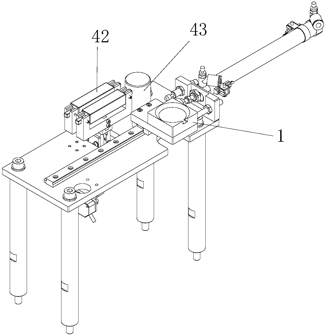
The invention discloses a lens dispensing and pressure maintaining device and method. The lens dispensing and pressure-holding equipment includes: a lens tooling for accommodating a lens and a lens barrel positioning tool for accommodating a lens barrel; a handling assembly configured to transfer the lens on the lens tooling to the lens barrel On the lens barrel in the positioning tooling; dispensing assembly, the dispensing assembly is configured to be able to perform dispensing on the lens barrel in the lens barrel positioning tooling; pressure holding assembly, the pressure holding assembly includes a pressure head and a drive machine, the driving machine is configured to be docked with the indenter, and the pressure holding component is configured to drive the indenter to be pressed on the The lens barrel is positioned on the tooling to apply a pressing force to the lens and the lens barrel. A technical effect of the present invention is that it can provide the required pressure and action time for the bonding of the lens barrel and the lens, so that the lens barrel and the lens can be firmly bonded.

Description

technical field [0001] The invention belongs to the technical field of electronic product processing, in particular, the invention relates to a lens dispensing and pressure-holding processing equipment and method. Background technique [0002] Virtual reality electronic equipment is a new type of application product that has appeared in this field in recent years. Users can experience a realistic audio-visual environment by wearing the equipment. In order to allow users to experience the stereoscopic image effect, such electronic products are usually provided with relatively complex optical devices such as lens barrels and lenses. [0003] At present, the installation method of the lens in virtual reality products is basically a manual operation, that is, the lens barrel is fixed manually, and then glue is dispensed by a glue dispenser, and then the lens is placed on the lens barrel manually, and then the assembled The product is placed on a special pressure-holding device....

Claims


Application Information

Patent Timeline
Patent Type & Authority Patents(China)
IPC IPC(8): G02B7/02
CPCG02B7/025
Inventor 李银静王清泉刘云海李帅张效治王伟
Owner GOERTEK OPTICAL TECH CO LTD
Learn More