
Lenticulation and 3D display

A technology of 3D display and lens grating, applied in the direction of diffraction grating, optics, instruments, etc., can solve the problems of poor display effect and small viewing angle of 3D display, and achieve the effect of enhancing display effect and increasing deflection angle

Inactive Publication Date: 2016-10-26
WUHAN CHINA STAR OPTOELECTRONICS TECH CO LTD
View PDF5 Cites 4 Cited by
  • Summary
  • Abstract
  • Description
  • Claims
  • Application Information

AI Technical Summary

Problems solved by technology

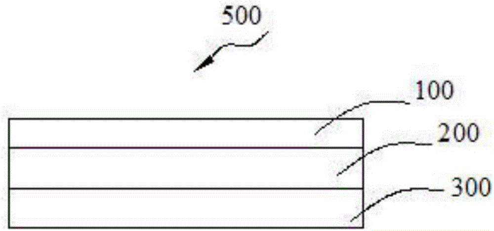
[0004] The purpose of the present invention is to provide a lenticular grating, which can solve the problems of the existing 3D display with a small viewing angle and poor display effect

Method used


Image

  • Lenticulation and 3D display
  • Lenticulation and 3D display
  • Lenticulation and 3D display

Examples


Embodiment Construction

[0024] The following will clearly and completely describe the technical solutions in the embodiments of the present invention with reference to the accompanying drawings in the embodiments of the present invention. Obviously, the described embodiments are only part of the embodiments of the present invention, not all of them. Based on the embodiments of the present invention, all other embodiments obtained by persons of ordinary skill in the art without making creative efforts belong to the protection scope of the present invention.

[0025] In addition, the following descriptions of the various embodiments refer to the attached drawings to illustrate specific embodiments in which the present invention can be implemented. The directional terms mentioned in the present invention, for example, "upper", "lower", "front", "rear", "left", "right", "inner", "outer", "side", etc., only is to refer to the direction of the attached drawings. Therefore, the direction terms used are for ...


PUM


Abstract

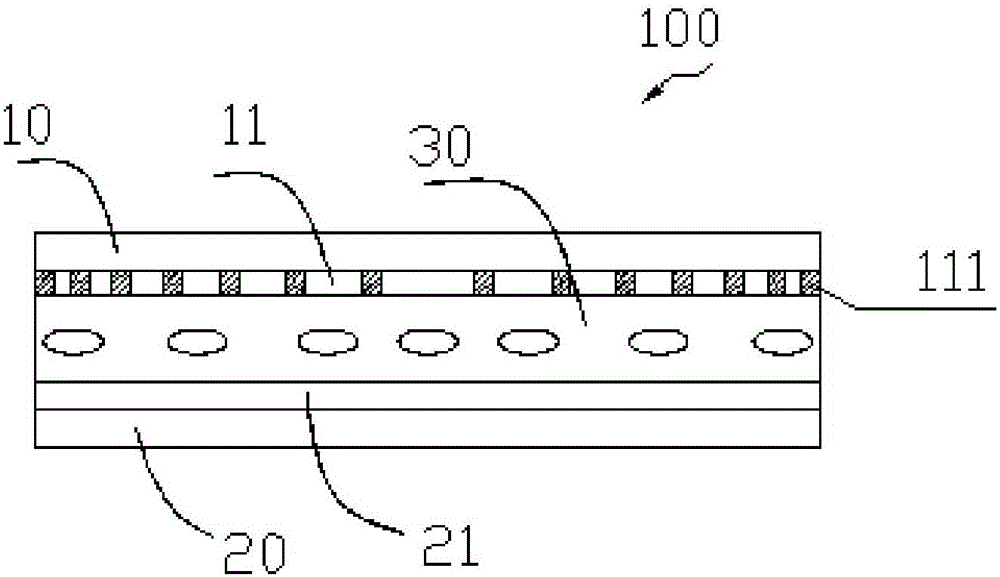
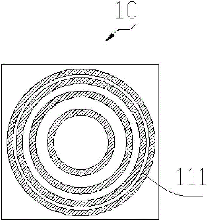
The present invention provides a lenticulation comprising a first substrate and a second substrate which are arranged oppositely, a first electrode layer positioned on the first substrate, a second electrode layer positioned on the second substrate, and a liquid crystal layer clamped between the first electrode layer and the second electrode layer; the first electrode layer comprises a plurality of ring electrodes; and projections of the plurality of ring electrodes on the first substrate are not overlapped. The first electrode layer of the lenticulation comprises the plurality of concentric ring electrodes, electric fields in more directions can be generated between common electrodes and pixel electrodes by using the concentric ring-shaped pixel electrodes, so that liquid crystal molecules have a plurality of deflection angles. Due to the fact that the deflection angles of the liquid crystal molecules are increased, multi-domain display is achieved, visual angles of a 3D display are enlarged, and the display effect of images is enhanced. The 3D display has larger visual angles, and therefore the display effect of the images is enhanced.

Description

technical field [0001] The invention relates to the technical field of liquid crystal display, in particular to a lens grating and a 3D display. Background technique [0002] Existing liquid crystal display modules generally include an array substrate and a color filter substrate arranged oppositely, a liquid crystal layer located between the array substrate and the color filter substrate, a common electrode and a pixel electrode, and polarizers respectively located on the array substrate and the color filter substrate. piece. [0003] The display principle of the existing liquid crystal display module is to convert natural light into linearly polarized light through the polarizer on the array substrate, apply voltage to the pixel electrode and the common electrode to form an electric field on both sides of the liquid crystal layer, and the liquid crystal molecules in the liquid crystal layer are under the action of the electric field. Rotation occurs, thereby changing the ...

Claims


Application Information

Patent Timeline
Patent Type & Authority Applications(China)
IPC IPC(8): G02F1/13G02F1/1343G02B5/18G02B27/22G02F1/29G02F1/1347G02B30/00
CPCG02B5/18G02F1/1313G02F1/134309G02F1/1347G02F1/29G02B2005/1804G02B30/27G02B5/1828G02B30/52G02F1/294G02B30/00H04N13/315G02F1/133526G02F2201/121G02F2201/122G02F2201/123
Inventor 谢畅
Owner WUHAN CHINA STAR OPTOELECTRONICS TECH CO LTD
Learn More