
Circuit module electromagnetic compatibility design method based on crystal oscillator frequency spectrum

An electromagnetic compatibility and circuit module technology, applied in the field of electromagnetic compatibility design of circuit modules, can solve the problems of prolonging the design cycle, difficult to sort out the types of interference sources one by one, large manpower, material resources, etc., saving time, cost, shortening Design cycle, the effect of improving design efficiency

Active Publication Date: 2016-10-26
BEIHANG UNIV
View PDF2 Cites 4 Cited by
  • Summary
  • Abstract
  • Description
  • Claims
  • Application Information

AI Technical Summary

Problems solved by technology

Although the electromagnetic compatibility problem can be divided into three parts, due to the complex electronic equipment and system components, it is difficult to sort out the types of interference sources one by one, and the coupling forms of electromagnetic energy are various and other objective facts. Comprehensive analysis leads to difficulties in EMC design
The traditional electromagnetic compatibility analysis and design methods require rich engineering experience and a good understanding of the equipment circuit structure, which puts forward higher requirements for engineers; at the same time, it often takes a lot of time to find the source of electromagnetic interference. Large manpower and material resources take a long time, thus prolonging the design cycle and increasing the project cost
These factors have caused the traditional EMC analysis and design method to have great limitations, and the solutions to different EMC problems have poor portability

Method used


Image

  • Circuit module electromagnetic compatibility design method based on crystal oscillator frequency spectrum
  • Circuit module electromagnetic compatibility design method based on crystal oscillator frequency spectrum
  • Circuit module electromagnetic compatibility design method based on crystal oscillator frequency spectrum

Examples


Embodiment Construction

[0036] The present invention will be further described below in conjunction with the accompanying drawings and embodiments, ie, the frequency source module.

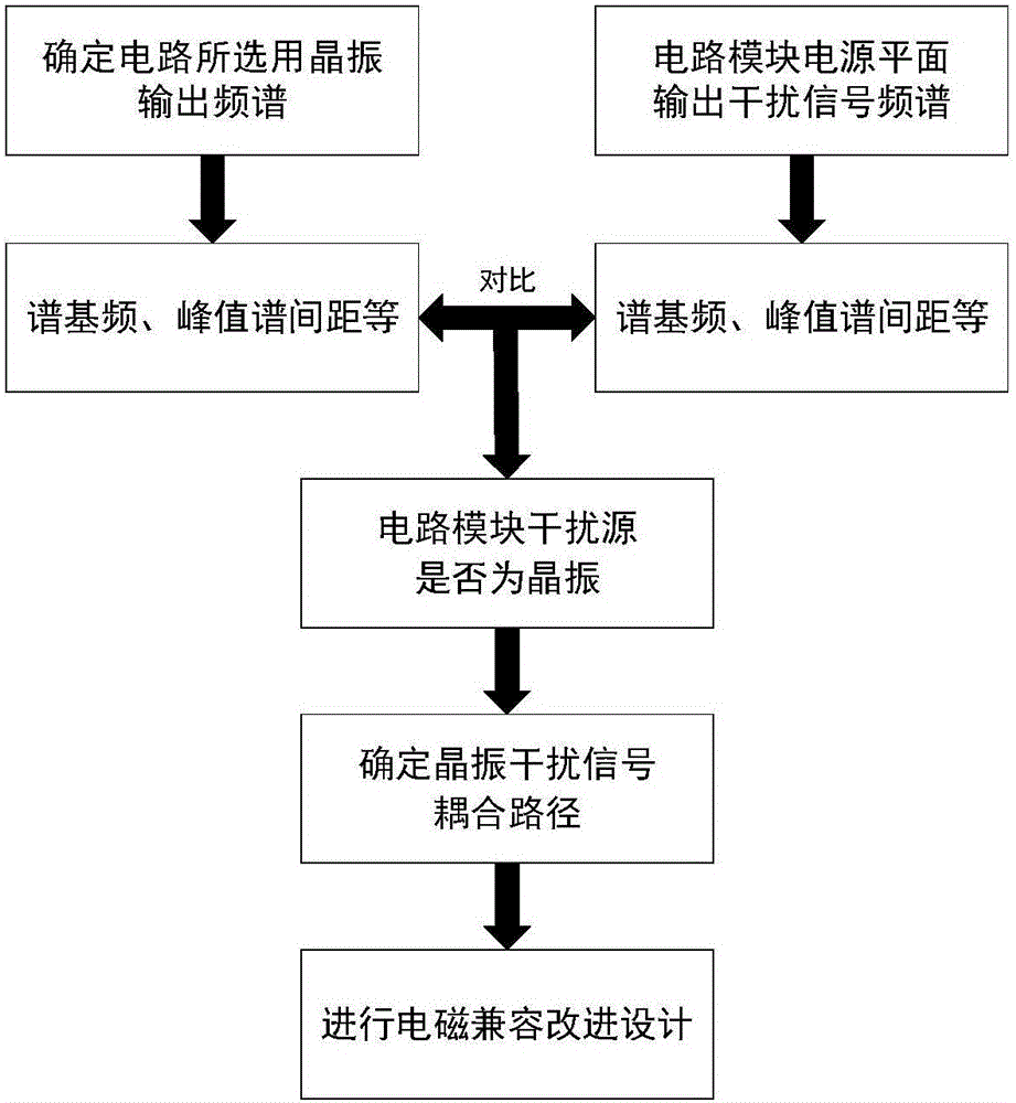
[0037] like figure 1 Shown, the concrete realization steps of the present invention are as follows:

[0038] Step 1: Determine the output spectrum and related parameters of the crystal oscillator selected by the frequency source module;

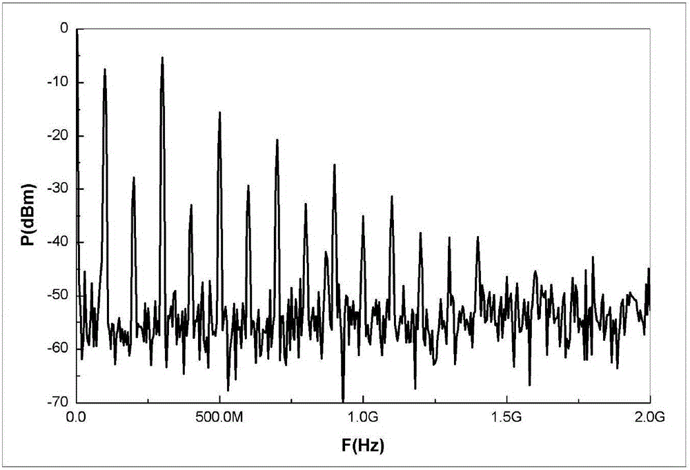
[0039] The output spectrum of an ideal crystal oscillator has only one peak, and the frequency point corresponding to this peak is the operating frequency point of the crystal oscillator. In fact, due to the nonlinear characteristics of the crystal oscillator circuit, there will be many harmonics in the output spectrum of the actual crystal oscillator, which is similar to a Comb, so the output spectrum of the crystal oscillator is called comb spectrum, such as figure 2 shown.

[0040] For the output spectrum of the crystal oscillator, the following parameters can be selected to desc...


PUM


Abstract

The present invention relates to a circuit module electromagnetic compatibility design method based on crystal oscillator frequency spectrum. The circuit module electromagnetic compatibility design method comprises the following steps of (1) determining output frequency spectrum and relevant parameters of a crystal oscillator selected by a circuit; (2) determining and verifying an interference source by testing a circuit module power plane output signal; (3) determining a coupling path of interference signals of the crystal oscillator; and (4) performing electromagnetic compatibility improved design. Starting with crystal oscillator frequency spectrum characteristics, the generic technology of the circuit module electromagnetic compatibility design is researched, and the electromagnetic compatibility key problem is solved. The purpose of the present invention is to provide a general technology means for the electromagnetic compatibility design of a modular circuit through electromagnetic compatibility design and analysis summary of a frequency source module, reliability of modular circuit design is increased when electromagnetic compatibility design efficiency is improved, and the circuit module electromagnetic compatibility design method is advantaged by universality and low cost.

Description

technical field [0001] The invention relates to an electromagnetic compatibility design method of a circuit module, more particularly, an electromagnetic compatibility design method of a circuit module based on a crystal oscillator output spectrum. It belongs to the field of electromagnetic compatibility. Background technique [0002] From the perspective of electromagnetic energy propagation, the electromagnetic compatibility problem can be divided into three components, namely interference sources, coupling channels, and sensitive equipment. Although the electromagnetic compatibility problem can be divided into three parts, due to the complex electronic equipment and system components, it is difficult to sort out the types of interference sources one by one, and the coupling forms of electromagnetic energy are various and other objective facts, it is difficult to truly achieve Comprehensive analysis leads to difficulties in EMC design. The traditional electromagnetic com...

Claims


Application Information

Patent Timeline
Patent Type & Authority Applications(China)
IPC IPC(8): G06F17/50
CPCG06F30/39
Inventor 陈爱新赵越苏东林应小俊吴文斌
Owner BEIHANG UNIV
Learn More