Method for generating vortex electromagnetic wave

A technology of vortex electromagnetic waves and array elements, which is applied in the directions of antenna arrays, circuits, and electrical components that are energized separately, to achieve the effects of simple and easy generation methods, rich theories and technologies, and flexible arrangement methods

Inactive Publication Date: 2016-10-26
UNIV OF ELECTRONICS SCI & TECH OF CHINA
View PDF2 Cites 11 Cited by
  • Summary
  • Abstract
  • Description
  • Claims
  • Application Information

AI Technical Summary

Problems solved by technology

[0005] Literature [Cheng L., Hong W., Hao Z.C., Generation of electromagnetic waves with arbitrary orbital angular momentum modes[J], Scientific reports, 2014:1-5] based on the lens principle to generate multiple OAM modes at the same frequency, but requires Precisely drill holes on the dielectric substrate to control the output phase, and it is an electrically large structure

Method used


Image

  • Method for generating vortex electromagnetic wave
  • Method for generating vortex electromagnetic wave
  • Method for generating vortex electromagnetic wave

Examples


Embodiment 1

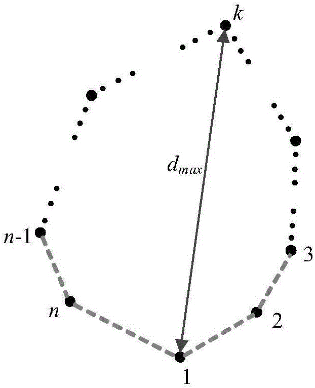
[0040] After determining the size of the array element, in this embodiment, 4 array elements are arranged on the edge of the triangle, the shape of the array is a right triangle, and the 4-element array antenna is located on the xoy plane. The CST simulation model is as follows Figure 5 shown. Considering the maximum spacing d of array antenna elements max For the influence of grating lobes, the distance d between adjacent array elements is taken as 0.1λ (λ is the free space wavelength corresponding to the resonance frequency), that is, 24mm, and the maximum distance between array elements is d max Less than one wavelength, ie 120mm. The excitation phase of the first array element is α 1 , control the excitation phases of other array elements to increase by 2πl / n=90° sequentially, so as to realize the vortex electromagnetic wave of OAM mode l=1. Figure 6 It is the electric field phase distribution diagram of embodiment 1, it can be seen that the electric field phase chang...

Embodiment 2

[0042] Figure 7 For the CST simulation model of embodiment 2, the difference with embodiment 1 is that the front shape is an acute triangle, Figure 8 It is the electric field phase distribution figure of embodiment 2.

Embodiment 3

[0044] Figure 9 For the CST simulation model of embodiment 3, the difference with embodiment 1 is that the front shape is an obtuse triangle, Figure 10 It is the electric field phase distribution figure of embodiment 3.


PUM


Abstract

The present invention discloses a method for generating a vortex electromagnetic wave. For an array antenna that has a total number of n array elements, excitations are applied to all array elements so as to generate the vortex electromagnetic wave, wherein the excitations have equal amplitude and sequentially have a difference of 2pi1/n in phase, an orbital angular momentum (OAM) mode of the vortex electromagnetic wave is 1 or -1 (1 or -1 changes clockwise or anticlockwise according to a phase difference or is controlled through ascending or descending of the phase difference), and the total number n of the array element and a topological charge 1 only needs to meet a relationship of |1|<n/2. The method for generating the vortex electromagnetic wave is simple to carry out and does not limit an array unit form, the array elements are arranged flexibly, vortex electromagnetic waves of different OAM modes can be generated by adjusting the number of the array elements and the array element arrangement manner, and vortex electromagnetic waves of multiple OAM modes that work simultaneously can be generated through proper combination.

Description

technical field [0001] The invention belongs to the field of electromagnetic field microwave technology, and in particular relates to a method for generating vortex electromagnetic waves. Background technique [0002] According to Maxwell's classical electromagnetic theory, electromagnetic radiation can carry energy and momentum at the same time, and momentum includes linear momentum and angular momentum. Angular momentum is divided into spin angular momentum (Spin Angular Momentum, SAM) and orbital angular momentum (Orbital Angular Momentum, OAM). As a basic physical property of electromagnetic waves, the eigenstates of OAM have the form The phase factor of , l is the mode of OAM, also called topological charge (Topological Charge, TC), which represents the spatial distribution of OAM. Ordinary electromagnetic wave OAM mode is l=0, and the equiphase plane is a plane; if the beam is distorted, the OAM mode of electromagnetic wave is not zero, which will cause the wave fro...

Claims


Application Information

Patent Timeline
Patent Type & Authority Applications(China)
IPC IPC(8): H01Q21/06H01Q21/20
CPCH01Q21/061H01Q21/20
Inventor 李家林张香博张一明王秉中
Owner UNIV OF ELECTRONICS SCI & TECH OF CHINA
Why Eureka
Try Eureka