Wheel disc type cable sheath chamfering cutter and chamfering method

A technology of cable sheath and chamfering tool, which is applied in the direction of cable installation, cable installation device, dismantling/armoring cable equipment, etc. It can solve the problem of poor chamfering or chamfering effect, damage to the internal structure of the cable, and cable insulation Hard layer and other problems, to achieve uniform chamfering, simple structure, the effect of protecting the wire core

Inactive Publication Date: 2016-10-26
GUANGZHOU PANYU CABLE WORKS
View PDF8 Cites 8 Cited by
  • Summary
  • Abstract
  • Description
  • Claims
  • Application Information

AI Technical Summary

Problems solved by technology

[0002] When an electrician installs or overhauls a power cable, it is necessary to chamfer the outer sheath of the cable end such as the insulating layer and the metal shielding layer covered by the cable to facilitate the connection of the line. The traditional cable end sheath chamfering tool uses an electrician's knife, a hook knife Or wallpaper knife and other tools for manual chamfering, but the efficiency of manual work is low, the effect of chamfering or chamfering is poor, and because the cable insulation layer is thick and hard, electricians often need to apply a lot of force during the operation. It takes a lot of force to chamfer the outer sheath of the cable end. This process is likely to cause damage to the internal structure of the cable. Therefore, it is extremely unsafe to use such chamfering tools to chamfer the outer sheath of the cable.

Method used


Image

  • Wheel disc type cable sheath chamfering cutter and chamfering method
  • Wheel disc type cable sheath chamfering cutter and chamfering method
  • Wheel disc type cable sheath chamfering cutter and chamfering method

Examples


Embodiment Construction

[0027] A kind of roulette type cable sheath chamfering tool of the present invention will be further described below in conjunction with accompanying drawing:

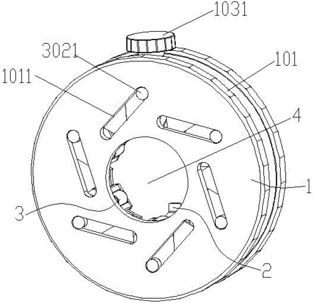
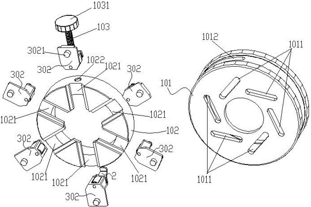
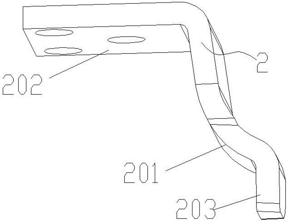
[0028] Such as Figure 1-4 Shown, a kind of roulette type cable sheath chamfering tool comprises ring tool rest 1, two chamfering blades 2 and six clamping devices 3 arranged on the ring tool rest 1, these six clamping devices 3 along The ring tool holder is evenly arranged in the circumferential direction; the clamping device 3 includes a locking block 302 and a clamping part 301 installed at the end of the locking block 302, and the clamping parts 301 of the six clamping devices 3 are surrounded by a clamping cable The clamping space 4, the locking block 302 is movably connected with the ring tool holder 1 through a locking device, and the locking device can adjust the locking block 302 to reciprocate synchronously along the radial direction of the ring tool holder 1 to adjust the clamping space 4 The size of the cl...


PUM


Abstract

The invention discloses a wheel disc type cable sheath chamfering cutter. The cutter comprises chamfering blades arranged on an annular knife rest and a wire clamping apparatus, wherein the annular knife rest comprises an annular chuck and an annular housing, the wire clamping apparatus can be adjusted to perform reciprocating movement along the radial direction of the annular chuck through a locking apparatus so as to enable the wire clamping apparatus to clamp a cable to be chamfered, and the cutter can move spirally relative to the cable so as to enable the chamfering blades to perform chamfering on the end sheath of the cable. The operation is simple, cables with different wire diameters can be chamfered, the chamfering depth is uniform and is adjustable and controllable, and the safety and the reliability are high. The invention further discloses a method for performing cable chamfering by use of the cutter. First of all, the wire clamping apparatus is adjusted through the locking apparatus so as to clamp the end of the cable to be chamfered, then the cutter is rotated and moved along the circumferential direction of the cable or the cable enables a cutting portion to be in contact with and cut the end sheath of the cable, and thus the end sheath of the cable is chamfered. The chamfering efficiency is high, and a wire core is protected.

Description

technical field [0001] The invention relates to the field of power tools, in particular to a wheel-type cable sheath chamfering tool and a chamfering method thereof. Background technique [0002] When an electrician installs or overhauls a power cable, it is necessary to chamfer the outer sheath of the cable end such as the insulating layer and the metal shielding layer covered by the cable to facilitate the connection of the line. The traditional cable end sheath chamfering tool uses an electrician's knife, a hook knife Or wallpaper knife and other tools for manual chamfering, but the efficiency of manual work is low, the effect of chamfering or chamfering is poor, and because the cable insulation layer is thick and hard, electricians often need to apply a lot of force during the operation. It takes a lot of force to chamfer the outer sheath of the cable end, and this process is likely to cause damage to the internal structure of the cable. Therefore, it is extremely unsafe...

Claims


Application Information

Patent Timeline
Patent Type & Authority Applications(China)
IPC IPC(8): H02G1/12
CPCH02G1/1226H02G1/1241
Inventor 胡超强尤占山王延发覃丹卢广业张仕欢陈雪儿郝燕张开拓易坡杜小建程雪丽
Owner GUANGZHOU PANYU CABLE WORKS
Why Eureka
Try Eureka