
Fingerprint identification module and flexible circuit board thereof

A fingerprint recognition module and flexible circuit board technology, applied in the field of biometrics, can solve the problems of small glue dispensing space, overflow of adhesive glue on the edge of fingerprint recognition chip, etc., and achieve the effect of preventing glue overflow

Inactive Publication Date: 2016-10-26
NANCHANG OUFEI BIOLOGICAL IDENTIFICATION TECH
View PDF0 Cites 7 Cited by
  • Summary
  • Abstract
  • Description
  • Claims
  • Application Information

AI Technical Summary

Problems solved by technology

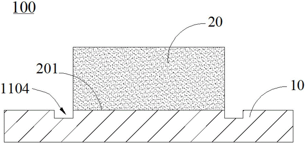
[0003] At present, the installation process of the fingerprint identification module is to weld the fingerprint identification chip on the circuit board through SMT (Surface Mount Technology, surface mount technology). The adhesive space is getting smaller and smaller, resulting in the overflow of adhesive glue on the edge of the fingerprint identification chip during the assembly process of the fingerprint identification module

Method used


Image

  • Fingerprint identification module and flexible circuit board thereof
  • Fingerprint identification module and flexible circuit board thereof
  • Fingerprint identification module and flexible circuit board thereof

Examples


Embodiment Construction

[0024] In order to make the above objects, features and advantages of the present invention more comprehensible, specific implementations of the present invention will be described in detail below in conjunction with the accompanying drawings. In the following description, numerous specific details are set forth in order to provide a thorough understanding of the present invention. However, the present invention can be implemented in many other ways different from those described here, and those skilled in the art can make similar improvements without departing from the connotation of the present invention, so the present invention is not limited by the specific implementations disclosed below.

[0025] As used herein, the terms "vertical", "horizontal", "left", "right", "upper", "lower" and similar expressions are for the purpose of illustration only and do not represent the only embodiment.

[0026] Unless otherwise defined, all technical and scientific terms used herein hav...


PUM

PropertyMeasurementUnit
Opening widthaaaaaaaaaa

Abstract

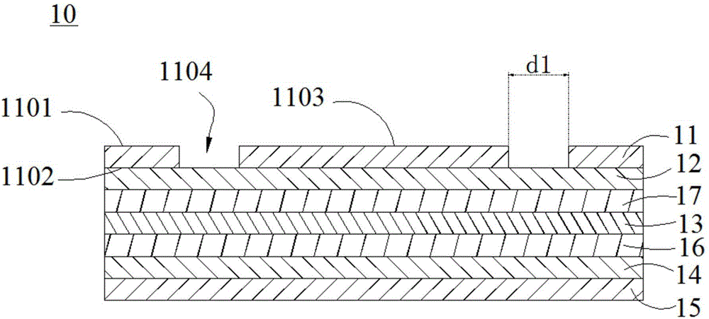
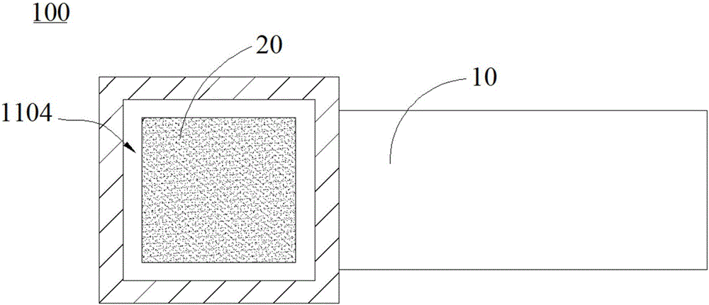
The invention discloses a flexible circuit board. The flexible circuit board comprises a first cover film layer which comprises a first top surface and a second surface arranged oppositely to the first top surface; and a first conductive layer which is arranged on the second surface of the first cover film layer, wherein the first top surface comprises a chip mounting area; a through groove around the chip mounting area is formed in the first top surface; and the through hole runs through the first top surface and the second surface. The through hole is used for containing adhesive glue which flow outwards when the fingerprint identification chip is fixed with the flexible circuit board, so that the condition that the adhesive glue overflows at the outer sidewall of the flexible circuit board in an assembling process of the fingerprint identification module can be prevented efficiently, and excessive glue also can be prevented efficiently. Meanwhile, the fingerprint identification module applying the flexible circuit board is also provided.

Description

technical field [0001] The invention relates to the field of biological identification, in particular to a fingerprint identification module and a flexible circuit board thereof. Background technique [0002] In recent years, with the continuous development of science and technology, the fingerprint identification module not only needs to meet higher identification performance, but also tends to develop in the direction of miniaturization. [0003] At present, the installation process of the fingerprint identification module is to weld the fingerprint identification chip on the circuit board through SMT (Surface Mount Technology, surface mount technology). The glue space is getting smaller and smaller, resulting in the overflow of the adhesive glue on the edge of the fingerprint recognition chip during the assembly process of the fingerprint recognition module. Contents of the invention [0004] Based on this, it is necessary to provide a fingerprint identification module...

Claims


Application Information

Patent Timeline
IPC IPC(8): H05K1/18H05K3/30G06K9/00
CPCH05K1/189H05K3/305H05K2201/09072G06V40/13
Inventor 刘忠杰
Owner NANCHANG OUFEI BIOLOGICAL IDENTIFICATION TECH
Learn More