Method for shaping patch type LED optical lens model

An optical lens and chip-type technology, which is applied in the field of chip-type LED optical lens molding, can solve the problems of easy falling off of optical lenses, slow production speed, and many operating procedures, so as to prevent glue overflow, fast production speed, and easy operation. The effect of fewer processes

Active Publication Date: 2009-05-27
HONGLI ZHIHUI GRP CO LTD
View PDF0 Cites 6 Cited by
  • Summary
  • Abstract
  • Description
  • Claims
  • Application Information

AI Technical Summary

Problems solved by technology

[0006] From the above, it can be seen that the use of secondary operations to glue optical lenses requires many operating procedures, slow production speed, and is not easy for mass production; since the optical lenses are bonded, they are not very firm, so when the temperature is too high (such as reflow soldering), , the optical lens is easy to fall off

Method used


Image

  • Method for shaping patch type LED optical lens model
  • Method for shaping patch type LED optical lens model
  • Method for shaping patch type LED optical lens model

Examples


Embodiment Construction

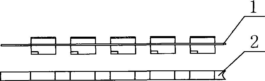
[0028] The present invention will be described in further detail below in conjunction with the accompanying drawings.

[0029] figure 1 , figure 2 , image 3 , Figure 4 , Figure 5 , Figure 6 and Figure 7 As shown, make a piece of steel sheet 2 with the same thickness as the light-transmitting shell on the patch-type LED plastic bracket 1, and then use the steel sheet to match the plastic bracket. The light-transmitting shell and the steel sheet are fully matched, so the transparent resin can be prevented Or stick transparent silicone on the light-transmitting shell.

[0030] SMD LED plastic bracket semi-finished products are dehumidified and baked in an oven to remove hidden moisture in the bracket to prevent air bubbles, and then use plasma cleaning to remove dust in the bracket to ensure the smoothness of the bracket and improve the transparent resin or transparent silicone and plastic bracket. The bonding performance of the light-transmitting shell, replace the ...


PUM


Abstract

The invention discloses a method for forming an LED optical lens mould of a SMD type. The method is characterized by comprising the following steps: (1) dehumidifying and plasma cleaning an LED bracket; (2) replacing a corresponding optical lens mould in a mould making machine; (3) arranging a sheet steel which prevents gel from overflowing on the LED bracket; (4) putting the optical lens mould on the mould making machine, and adding transparent resin or transparent gel; (5) roasting in a oven; and (6) finally, cutting clubfoot. The sheet steel is a bulk substrate, wherein the substrate is distributed with holes which have the same thickness with a translucent shell on the LED bracket; the substrate is distributed with the holes in matrix form; and the substrate is a plate. The method has the advantages that the method makes transparent resin or transparent silica gel and the translucent shell on the LED plastic bracket form the optical lens one time, and speeds up the production, and makes the optical lens bond firmly and not easy to fall off.

Description

technical field [0001] The invention relates to a method for molding a patch type LED optical lens. Background technique [0002] SMD LED (SMD LED) is a new type of surface-mounted semiconductor light-emitting device. The package of SMD LED generally has two structures: one is PCB chip LED (commonly known as CHIP LED); One is metal plastic bracket LED (commonly known as TOP LED). Bracket LEDs generally have two packaging types: plane glue filling and glued optical lens. When using products that require a large light-emitting surface and a short light projection distance, you can use plane glue-filling package bracket-type LEDs, because of its luminous angle. Larger, generally around 120 degrees; but when the light is required to be concentrated and the light projection distance is long, it is necessary to use a bracket-type LED with a small light-emitting angle and an optical lens package. [0003] This kind of bracket-type LED packaged with optical lens, because the light...

Claims


Application Information

Patent Timeline
Patent Type & Authority Applications(China)
IPC IPC(8): H01L33/00H01L21/50H01L33/58
CPCH01L24/97H01L2224/48091H01L2224/48247H01L2924/181
Inventor 李国平
Owner HONGLI ZHIHUI GRP CO LTD
Why Eureka
Try Eureka