
Headrest and vehicle seat

A technology for headrests and seat cushions, which is applied to vehicle seats, headrests, and vehicle parts, and can solve problems such as functional degradation, polyurethane pads that are difficult to transmit sound, and passengers who are difficult to hear speaker sounds, so as to prevent Effects of sound pressure and sound quality degradation

Active Publication Date: 2016-10-26
TACHI S CO LTD
View PDF14 Cites 9 Cited by
  • Summary
  • Abstract
  • Description
  • Claims
  • Application Information

AI Technical Summary

Problems solved by technology

[0005] However, since the urethane backing is difficult to transmit sound, when the urethane backing is placed in front of the speaker, it is difficult for passengers to hear the sound from the speaker.
Even if the thickness of the polyurethane pad is thinned and the speaker is placed on the back side of the polyurethane pad, the sound can be heard with a certain sound pressure, but in this case, the function of holding the head and the body is reduced. The problem

Method used


Image

  • Headrest and vehicle seat
  • Headrest and vehicle seat
  • Headrest and vehicle seat

Examples


Deformed example 1

[0078] In the above embodiment, if Figure 4 As in the illustrated headrest 4A, the shape of the sound-insulating pad 16 is such that it expands in the left-right direction in the horizontal plane as it moves away from the speakers 25a and 25b. However, it is also possible to substitute Figure 7 Like the illustrated headrest 4B, the sound-insulating pad 16 is formed into a shape having a constant width W0 in the left-right direction, that is, a substantially rectangular parallelepiped shape. Also in this case, the sound emitted from the speakers 25a, 25b can be made directional by the duct structure 18 composed of the fiber backing board 15 and the sound insulation backing boards 16, 16a, 16b. In addition, the sound insulation spacer 16 can prevent the sound from the speaker 25a and the sound from the speaker 25b from interfering with each other, and as a result, the ability to separate the left and right sounds can be kept high.

Deformed example 2)

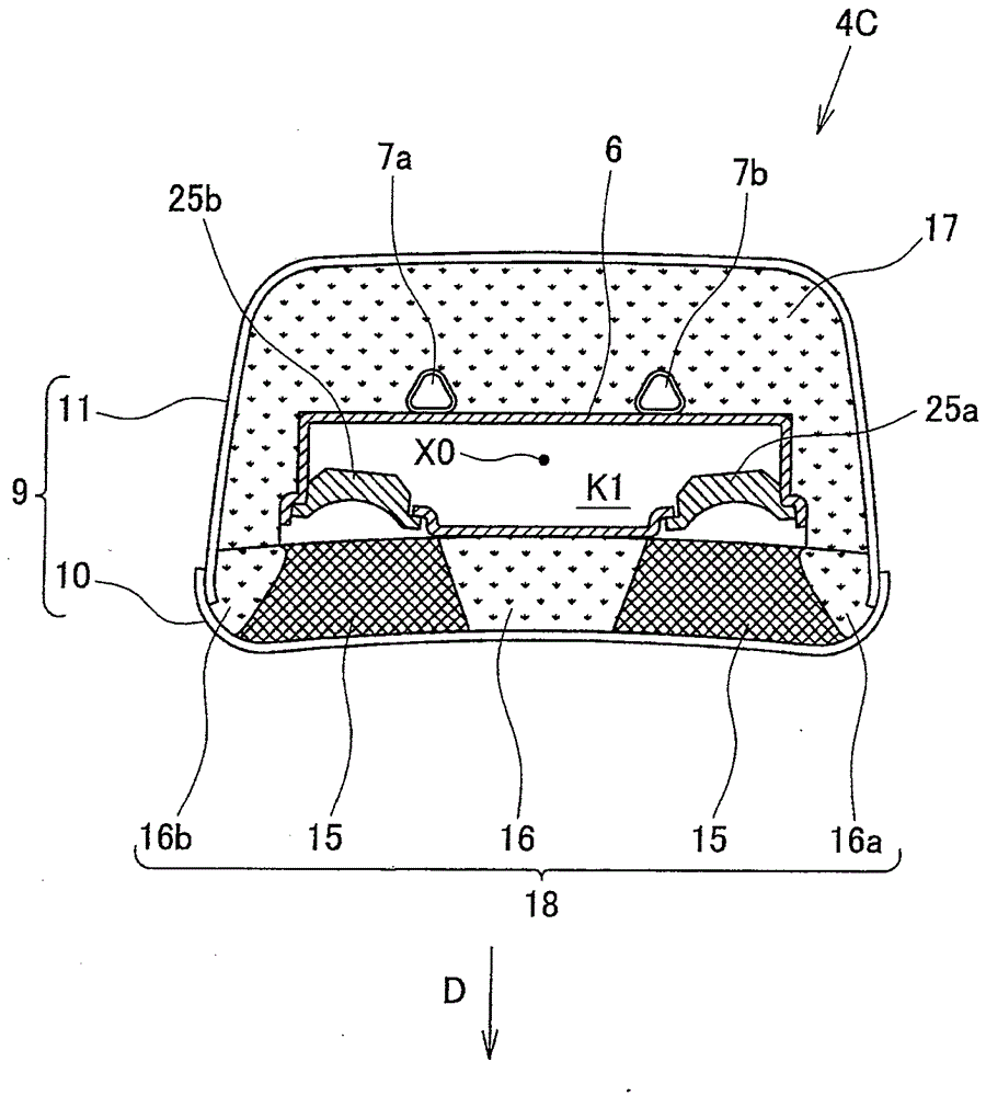
[0080] In the above embodiment, if Figure 4 As in the illustrated headrest 4A, the shape of the sound-insulating pad 16 is made into a shape that expands in the left and right directions in the horizontal plane as it moves away from the speakers 25a, 25b, or a shape such as Figure 7 As in the illustrated headrest 4B, the shape of the sound-insulating pad 16 is such that the width W0 in the left-right direction is constant. However, it is also possible to substitute Figure 8 As in the illustrated headrest 4C, the sound-insulating pad 16 has a shape that narrows toward the center portion in the horizontal plane as it goes forward indicated by the arrow D. As shown in FIG. Also in this case, the sound emitted from the speakers 25a, 25b can be made directional by the duct structure 18 composed of the fiber backing board 15 and the sound insulation backing boards 16, 16a, 16b. In addition, the sound insulation spacer 16 can prevent the sound from the speaker 25a and the sound ...

Deformed example 3)

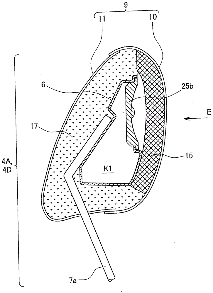
[0082] In the above embodiment, if Figure 4 , Figure 5 and Image 6 As shown, the duct structure 18 is constituted by a substantially rectangular fiber mat 15 and sound-insulating mats 16, 16a, 16b. It is also possible to use instead Figure 4 , Figure 5 and Figure 9 The pipeline structure of this modification of the structure shown. Figure 9 is according to Figure 4 The longitudinal section structure of the CC line.

[0083] The duct structure used in the headrest 4D of this modified example has a fiber backing board 15 and sound-insulating backing boards 16, 16a, 16b, which is the same as Figure 4 , Figure 5 and Image 6 The piping shown is of the same construction. This modification and Figure 4 , Figure 5 and Image 6 The difference between the shown pipe structures is that the sound insulation pad 16 sandwiched by the left and right fiber pads 15, 15 is as follows: Figure 9 It is integral with the elastomer 17 of the rear surface as shown. With t...


PUM


Abstract

Through the present invention, a person does not feel discomfort when touching a speaker-incorporating headrest, the speaker is arranged near the person, whereby the headrest is formed having a small size, and the sound pressure or sound quality of sound from the speaker is prevented from decreasing. The present invention has a plurality of speakers 25a, 25b, fiber pads 15 provided in front of the speakers 25a, 25b, a sound-insulating pad 16 provided between the fiber pads 15, and a cover 9 for covering the speakers 25a, 25b / fiber pads 15 / sound-insulating pad 16, the fiber pads 15 are formed from an elastic material having an internal three-dimensional network structure, and the sound-insulating pad 16 is formed from an elastic material for suppressing transmission of sound.

Description

technical field [0001] The present invention relates to a headrest on which a passenger seated in a vehicle seat rests against the back of the head. Furthermore, the present invention relates to a vehicle seat on which a passenger seated in a vehicle is seated. Background technique [0002] Conventionally, in headrests for vehicle seats, there is known a structure in which speakers are provided at lateral positions on the left and right of the portion where the occupant's head rests (for example, refer to Patent Document 1 (Japanese Utility Laid-Open No. 4-104948 Bulletin)). In addition, there is conventionally known a structure in which speakers are provided on the upper portion of the seat back of a vehicle seat and at lateral positions on the left and right of the occupant's neck (for example, refer to Patent Document 2 (Japanese Utility Laid-Open No. 6-086612)) . [0003] However, in the headrest of Patent Document 1, since the overall size of the speaker is large, th...

Claims


Application Information

Patent Timeline
Patent Type & Authority Applications(China)
IPC IPC(8): B60N2/48A47C7/38B60R11/02B60N2/879
CPCB60N2002/899B60N2/879B60R11/0217B60R2011/0017H04R1/025H04R5/023H04R2499/13
Inventor 伊藤康行长泽隆彦高田直树中岛文彬石川贵夫
Owner TACHI S CO LTD
Learn More