Oil gas recovery device
A recovery device, oil and gas technology, applied in gas treatment, steam condensation, transportation and packaging, etc., can solve the problems of lack of recovery filtration effect, insufficient gas condensation, difficult maintenance life, etc., to achieve good sealing reliability and easy maintenance , long service life effect
- Summary
- Abstract
- Description
- Claims
- Application Information
AI Technical Summary
Problems solved by technology
Method used
Image
Examples
Embodiment 1
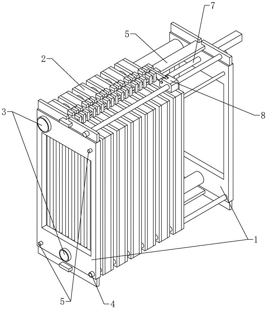
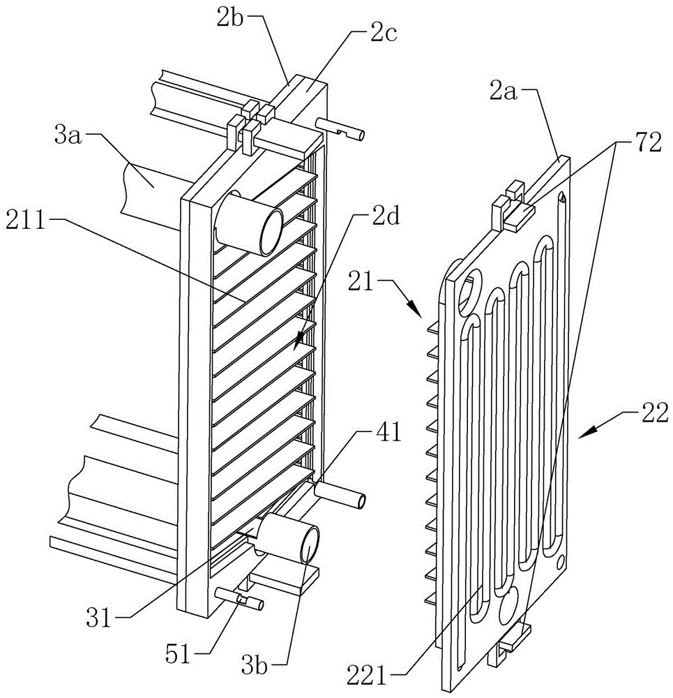
[0039] according to Figure 1 to Figure 5 As shown, an oil and gas recovery device includes: a shelf plate 1, several condensation filter units 2, an air pipe 3, a recovery pipe 4, a condensation pipe 5, a slide rail 6 and a pressing mechanism 7.
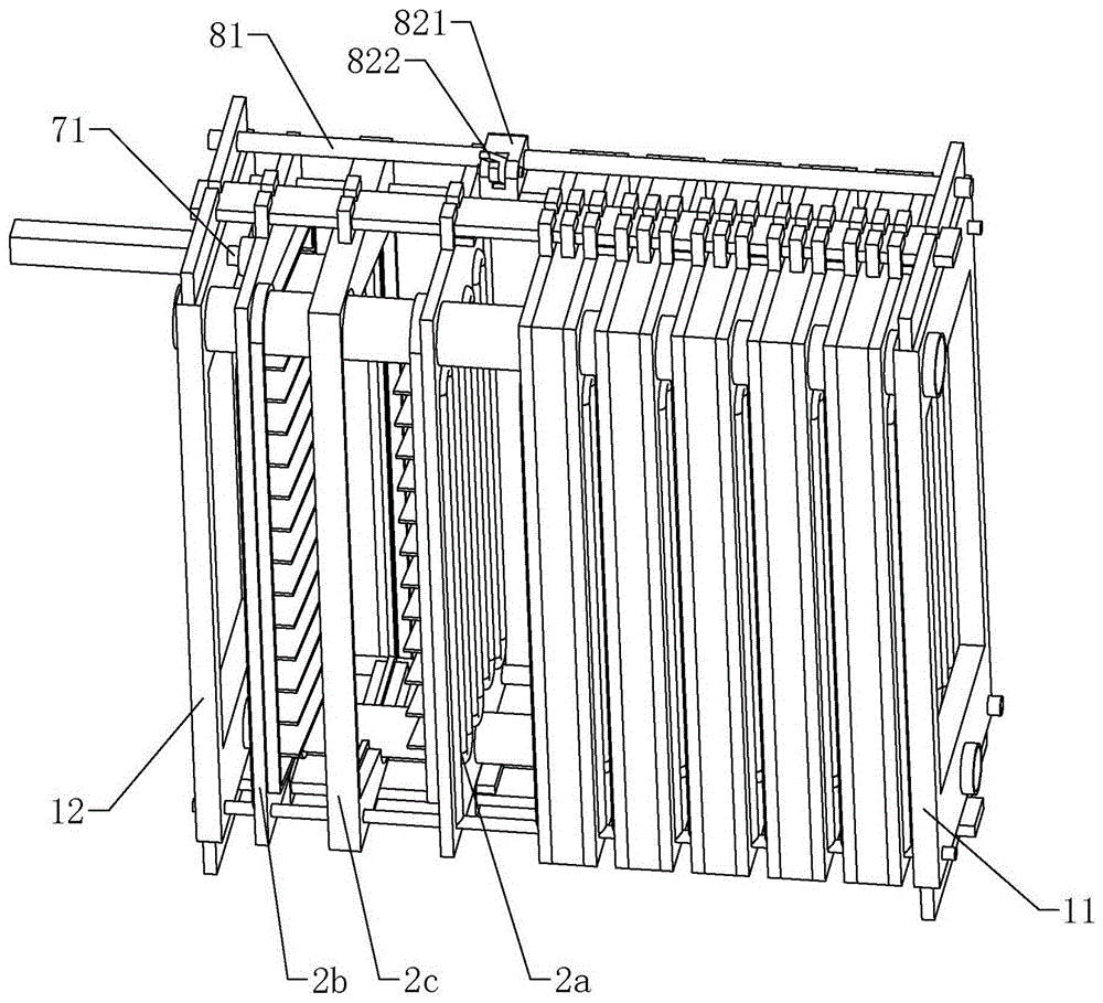
[0040] The shelf 1 includes the first shelf 11 and the second shelf 12 respectively arranged at both ends of the device, the condensation filter unit 2 is arranged between the first shelf 11 and the second shelf 12, the air pipe 3, the recovery pipe 4, the condensation pipe 5 and the two ends of the slide rail 6 are respectively fixed on the first shelf 11 and the second shelf 12, and the condensate filter unit 2 slides between the first shelf 11 and the second shelf 12 through the slide rail 6 and on the Fixed position under the effect of pressing mechanism 7.
[0041]The condensation filter unit 2 includes a first filter plate 2a, a second filter plate 2b and a sealing backing plate 2c, the periphery of the first filter plate 2a ...
Embodiment 2
[0047] The difference from the above-mentioned embodiment 1 is that, according to Figure 5 As shown, there is a cavity 2c11 inside the outer cushion area 2c1, and a spring 2c12 is arranged in the cavity 2c11, and the spring 2c12 is evenly distributed in the frame shape of the outer cushion area 2c1, and under the action of the pressing mechanism 7, the spring in the cavity 2c11 2c12 is compressed, which makes the combination of the outer pad area 2c1 and the first filter plate 2a and the second filter plate 2b more tightly, which further improves the sealing performance and prevents the leakage of oil and gas. , In addition, the thickness of the slider 26 located at the sealing backing plate 2c is smaller than the thickness of the outer pad area 2c1, so as to avoid affecting the clamping effect between the first filter plate 2a and the second filter plate 2b due to the collision between the sliders 26 , to ensure the tightness of the device.
Embodiment 3
[0049] The difference from the above-mentioned embodiment 1 or 2 is that according to figure 1 , figure 2 As shown, a separation mechanism 8 is also provided on the shelf plate 1. The separation mechanism 8 includes a slide bar 81 and a separator 82. The slide bar 81 is a screw rod. The separator 82 includes a slide table 821 and a hinged joint arranged on the slide bar 81. The driving rod 822 on the slide table 821 is controlled by a motor arranged on the slide table 821, and can rotate up and down, thereby selecting the slide block 26 to move.
[0050] In the device cleaning process of this embodiment, the difference from Embodiment 1 is that when the device is cleaned, after the pressure rod 71 is loosened, the first filter plate 2a, the second filter plate 2b and the sealing backing plate of the condensation filter unit 2 2c are separated one by one under the drive of separation mechanism 8, which saves manpower.
PUM
 Abstract
Description
Claims
Application Information
 - R&D
- Intellectual Property
- Life Sciences
- Materials
- Tech Scout
- Unparalleled Data Quality
- Higher Quality Content
- 60% Fewer Hallucinations
Browse by: Latest US Patents, China's latest patents, Technical Efficacy Thesaurus, Application Domain, Technology Topic, Popular Technical Reports.
© 2025 PatSnap. All rights reserved.Legal|Privacy policy|Modern Slavery Act Transparency Statement|Sitemap|About US| Contact US: help@patsnap.com


