Signal Extraction Method of Electromagnetic Flowmeter

An electromagnetic flowmeter and signal extraction technology, which is applied in the application of electromagnetic flowmeters to detect fluid flow, volume/mass flow generated by electromagnetic effects, etc., can solve the problems of conflicting power saving requirements and increased excitation power, and achieve improved S /N, the effect of reducing power and reducing output fluctuations

Inactive Publication Date: 2016-11-02
TOKYO KEISO
View PDF9 Cites 4 Cited by
  • Summary
  • Abstract
  • Description
  • Claims
  • Application Information

AI Technical Summary

Problems solved by technology

[0006] However, in the countermeasure (1), the power consumption due to the excitation increases, which is contrary to the demand for power saving.

Method used


Image

  • Signal Extraction Method of Electromagnetic Flowmeter
  • Signal Extraction Method of Electromagnetic Flowmeter
  • Signal Extraction Method of Electromagnetic Flowmeter

Examples


Embodiment Construction

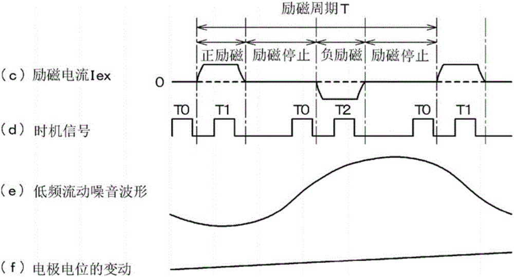
[0042] The circuit configuration of the electromagnetic flowmeter of this reference example is basically the same as Figure 4 The conventional examples are the same, but the sampling timing generated by the timing signal generating circuit 10 and the calculation method in the CPU 7 are different from the conventional examples.

[0043] figure 1 It is the waveform diagram of the exciting current waveform and the timing signal of the reference example. figure 1 middle, figure 1 (c) is the excitation current waveform output by the excitation circuit 9; figure 1 (d) is the timing signal output by the timing signal generating circuit 10; figure 1 (e) indicates the magnitude of the low-frequency flow noise mentioned in (iii) above; figure 1 (f) shows the electrode potentials of the slowly varying electrodes 5 a and 5 b described in (i) above.

[0044] In the excitation current waveform figure 1In (c), an excitation stop section is provided between the positive excitati...


PUM


Abstract

The invention provides a signal extraction method of an electromagnetic flowmeter, in order to improve S/N according to an excitation method with low powder consumption and perform signal processing with less output fluctuation. In an exciting current waveform (c), an excitation stop period is arranged between a positive excitation interval and a negative excitation interval. Sampling times T1 and T2 of the positive and negative excitation intervals and sampling time T0 of the excitation stop period are determined according to a timing signal (d), and the flow velocity and the flow rate are obtained from the times T1 and T2 and the difference between the electrode potentials extracted at the time T0. In addition to the electromotive force which is used as a flow rate signal, the electrode potentials sampled at times T0, T1, T2 include flow noise (e) superimposed on the electrode, and the electrode potential (f) which fluctuates slowly are also sampled. By obtaining the difference between the electrode potentials at the time T1, T2 and the preceding time T0 and obtaining the flow rate with a short sampling period, correct flow velocity and flow rate are obtained, and flow noise (e) and electrode potential fluctuation (f) cancel each other and can be effectively removed.

Description

technical field [0001] The present invention provides a signal extraction method of an electromagnetic flowmeter, which can remove the influence of noise and obtain a flow signal with good accuracy. Background technique [0002] In an electromagnetic flowmeter, an excitation coil is used to apply an alternating magnetic field to a conductive fluid flowing through a measuring tube, and according to Faraday's law, the flow velocity of the fluid is obtained based on the electromotive force generated in a direction perpendicular to the direction of the fluid and the direction of the magnetic field. . [0003] In this electromagnetic flowmeter, since the signal electromotive force obtained is weak, in order to improve the signal to noise ratio S / N (signal to noise ratio) and stabilize the output, the following two countermeasures have been taken for a long time. [0004] (1) A large excitation current flows to form a strong magnetic field, which increases the generated electromo...

Claims


Application Information

Patent Timeline
Patent Type & Authority Applications(China)
IPC IPC(8): G01F1/58
CPCG01F1/58
Inventor 鸟丸尚竹田修逢强陈立功陆经伟姚迪斐
Owner TOKYO KEISO
Why Eureka
Try Eureka