Electronic component joint

A technology for electronic components and bonding heads, which is used in the assembly of printed circuits with electrical components, metallurgical bonding, etc., can solve the problems of equipment operation performance damage, solder bump collapse, productivity deterioration, etc., to reduce thermal expansion fluctuations and improve productivity. , the effect of suppressing bump collapse

Active Publication Date: 2016-11-02
PANASONIC INTELLECTUAL PROPERTY MANAGEMENT CO LTD
View PDF6 Cites 3 Cited by
  • Summary
  • Abstract
  • Description
  • Claims
  • Application Information

AI Technical Summary

Problems solved by technology

[0015] In this way, if the ceramic heater 92 is provided with a sufficient thickness, the capacity of the ceramic heater 92 will increase, and thus a large thermal expansion change will occur in the ceramic heater 92 during heating and cooling, and fine solder bumps will be generated during the bonding process. collapse, making good joints sometimes becomes difficult
[0016] In addition, the increase in the size of the head greatly deteriorates the operation performance of the equipment itself, so the productivity deteriorates.
In addition, in maintainability etc., since water etc. are used, the maintainability at the time of a head failure etc. deteriorates, and here also becomes the factor which significantly deteriorates productivity.

Method used


Image

  • Electronic component joint
  • Electronic component joint
  • Electronic component joint

Examples


Embodiment Construction

[0085] Embodiments according to the present invention will be described in detail below with reference to the drawings.

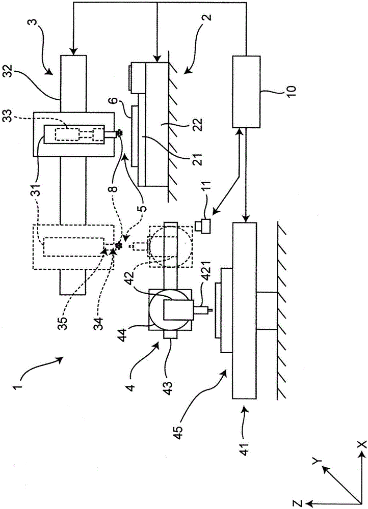
[0086] First, the main reference figure 1 The structure of the electronic component mounting apparatus 1 provided with the electronic component bonding head in this embodiment is demonstrated.

[0087] in, figure 1 It is a schematic front view of the electronic component mounting apparatus 1 provided with the electronic component bonding head in embodiment concerning this invention.

[0088] The electronic component mounting apparatus 1 is a so-called flip-chip mounting apparatus that simultaneously mounts and bonds electronic components to fine electronic components used in systems such as LSI (Large Scale Integration) and a circuit board 6 such as a printed circuit board as an object. .

[0089] The electronic component mounting apparatus 1 includes a substrate holding unit 2 , a component mounting unit 3 having a bonding head 5 , a component supply ...


PUM


Abstract

The present invention provides an electronic component joint. The electronic component joint includes a glass tool portion (51) having a heating electrode portion (512) for heating the electronic component (8); and a cooling module portion (52) for cooling the glass tool portion. The glass tool portion has a first glass portion (513) for holding one side of the electronic component with respect to the heating electrode portion, and a second glass portion (511) for holding arrangement on the opposite side of the side of the electronic component with respect to the heating electrode portion and connected to the cooling module portion. The thickness T1 of the first glass portion is 0.2 to 2 mm, and the thickness T2 of the second glass portion is 1.2 to 25 times the thickness of the first glass portion. By reducing the thermal expansion fluctuation in the process of rapid heating and rapid cooling, it is possible to reduce the size and increase the productivity remarkably.

Description

technical field [0001] The present invention relates to an electronic component bonding head used when mounting and bonding electronic components on a circuit board. Background technique [0002] Conventionally, in an apparatus for mounting an electronic component on a circuit board such as a printed circuit board, various methods of joining electrodes of an electronic component held by a component holding unit and electrodes of a circuit board are used. As one of the methods capable of joining electronic components in a short time, there is known a method of joining a metallic material represented by solder by melting a metal material by heating a head. [0003] In recent years, there has been a processing method of directly mounting an electrode pad surface of an electronic component on a circuit board represented by flip-chip mounting. In this processing method, since the stress at the time of bonding can be relieved by solder bonding and cost reduction is desired, a bon...

Claims


Application Information

Patent Timeline
Patent Type & Authority Applications(China)
IPC IPC(8): H05K3/34
CPCH05K3/34H05K2203/04
Inventor 蛯原裕广濑贵之
Owner PANASONIC INTELLECTUAL PROPERTY MANAGEMENT CO LTD
Why Eureka
Try Eureka