Reforming Furnace

Pending Publication Date: 2022-05-19
OSAKA GAS CO LTD
View PDF0 Cites 0 Cited by
  • Summary
  • Abstract
  • Description
  • Claims
  • Application Information

AI Technical Summary

Benefits of technology

[0044]Namely, since the air preheating heat exchanger has a cylindrical configuration in which air is caused to flow between a cylindrical inside wall and a cylindrical outside wall, this air preheating heat exchanger acts as a heat insulator covering the inner face of the outer wall, so that further heat insulating performance for suppressing escape of heat generated by combustion of the burner to the outside of the furnace body can be achieved.
[0045]Moreover, air introduced through the air introducing portion provided at a lower side portion of the air preheating heat exchanger flows to the burner through the plurality of air supplying pipes connecting between the upper side portion of the air preheating heat exchanger and the burner. And, since the plurality of air supplying pipes are disposed in a radial layout along the circumference of

Problems solved by technology

Due to this, there was an inconvenience that desirable reduction in the amount of combustion of the burner required for maintaining a catalyst inside the reforming reaction tube at an appropriate reaction temperature (e.g. 650° C.) cannot b

Method used


Image

  • Reforming Furnace
  • Reforming Furnace

Examples


Example

[0050]Next, an embodiment of the present invention will be explained with reference to the accompanying drawings.

[0051](General Configuration of Reforming Device)

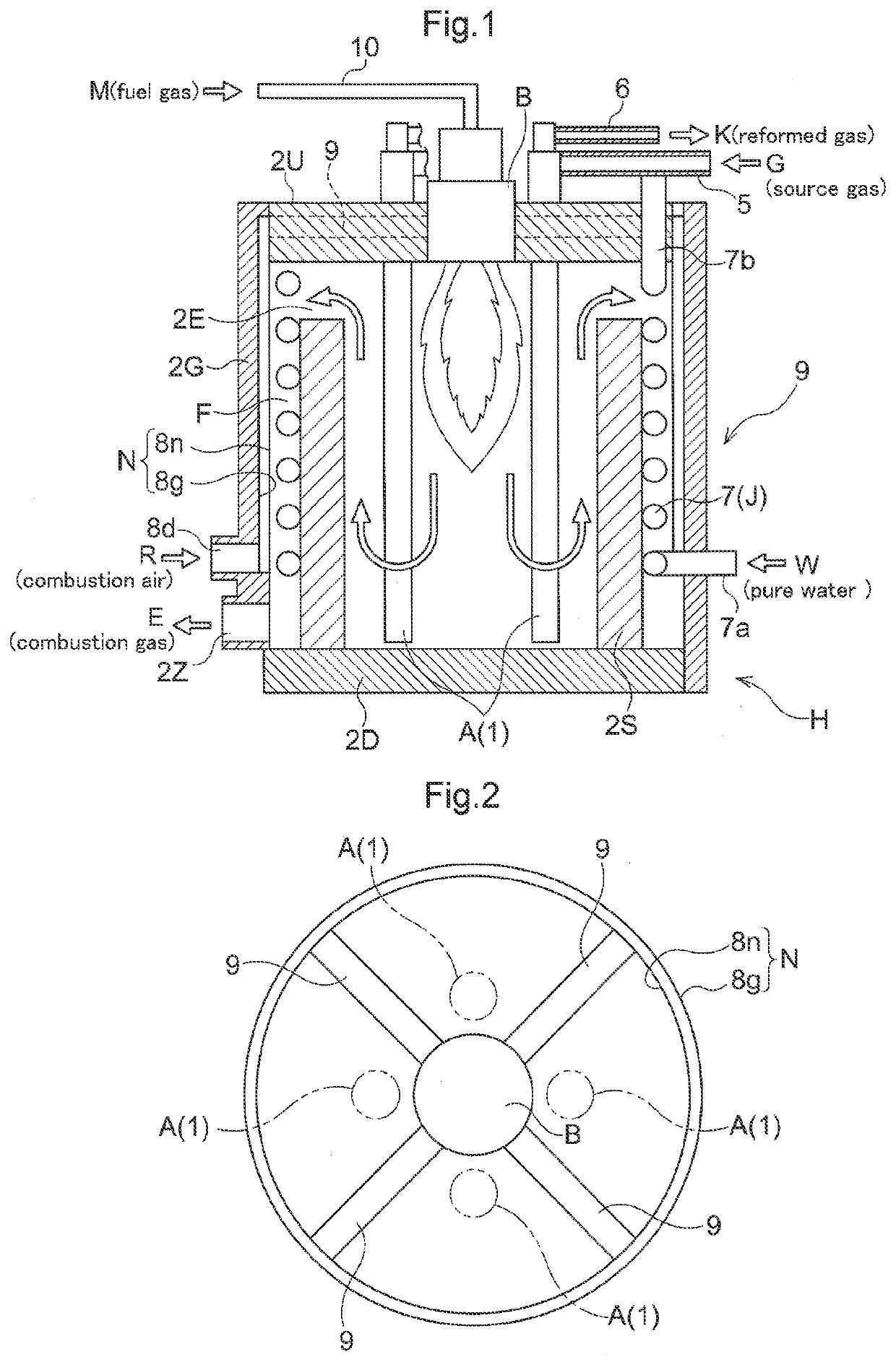
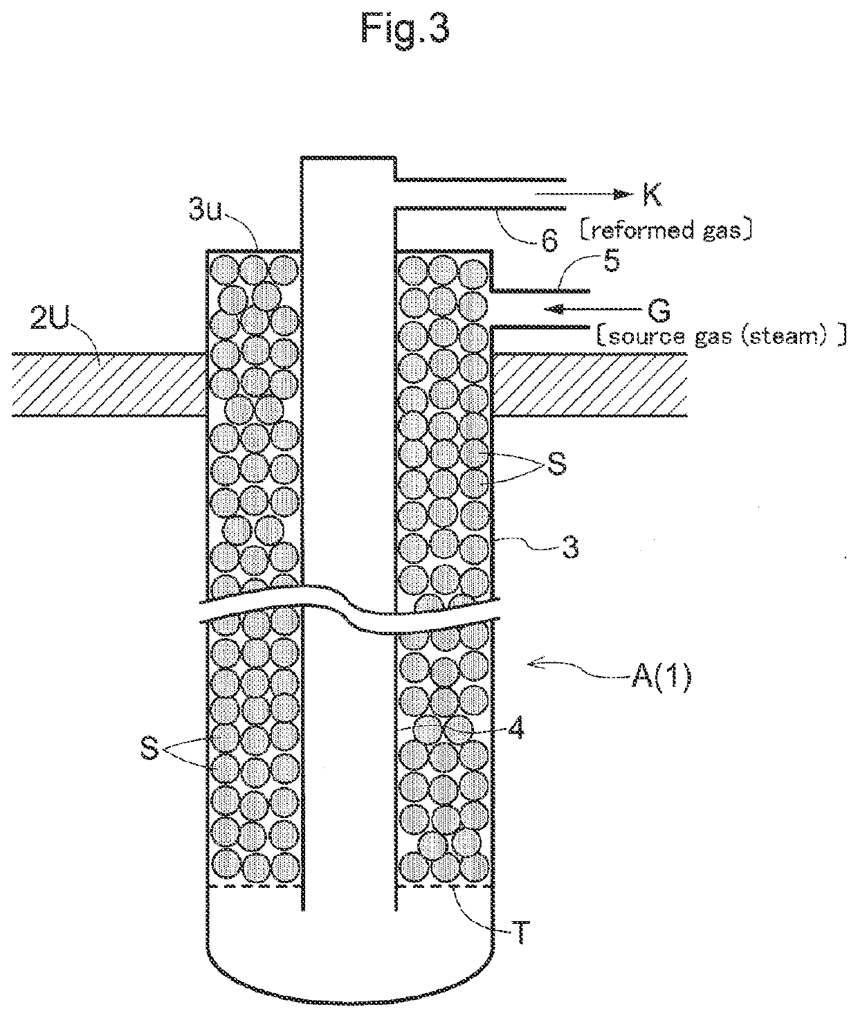
[0052]As shown in FIG. 1, a reforming furnace is used for reforming a source gas G which can be a hydrocarbon-based gas such as a natural gas, naphtha, etc. into a reformed gas K having enriched hydrogen content through a steam reforming treatment thereof and the reforming furnace includes a furnace body H provided with a reforming reaction tube 1 and a burner B for heating this reforming reaction tube 1.

[0053]The furnace body H includes a ceiling wall 2U, a bottom wall 2D, and a cylindrical lateral wall 2S disposed between the ceiling wall 2U and the bottom wall 2D.

[0054]And, at a center portion of the ceiling wall 2U of the furnace body H, a burner B is provided to effect combustion downwards, and at an upper side portion of the lateral wall 2S, a discharging portion 2E is formed as an opening through which combustion gas...


PUM


Abstract

At a center portion of a ceiling wall of a furnace body having a lateral wall between the ceiling wall and a bottom wall, there is a burner that combusts downwards. A reforming reaction tube is provided in a circumference of the burner to carry out a steam reforming treatment on a source gas. A discharging portion is an opening at an upper side portion of the lateral wall for discharging combustion gas of the burner. A cylindrical outer wall is disposed at an outer side portion of the lateral wall. In an outside space formed between the lateral wall and the outer wall, there is a steam generating heat exchanger generating steam or a mixture gas of a source gas and steam. At a lower side portion of the outer wall, there is outside discharging opening discharging the combustion gas which flows through the outside space.

Description

CROSS-REFERENCE TO RELATED APPLICATIONS[0001]This application is the United States national phase of International Application No. PCT / JP2020 / 013549 filed Mar. 26, 2020, and claims priority to Japanese Patent Application No. 2019-058844 filed Mar. 26, 2019, the disclosures of which are hereby incorporated by reference in their entirety.BACKGROUND OF THE INVENTION1. Field of the Invention[0002]The present invention relates to a reforming furnace including:[0003]a burner combusting downwards and provided at a center portion of a ceiling wall of a furnace body having a cylindrical lateral wall disposed between the ceiling wall and a bottom wall;[0004]a reforming reaction tube provided in a circumference of the burner in suspension from the ceiling wall and configured to carry out a steam reforming treatment on a hydrocarbon-based gas as a source gas; and[0005]a discharging portion provided as an opening at an upper portion of the lateral wall for discharging combustion gas of the burne...

Claims


Application Information

Patent Timeline
IPC IPC(8): B01J19/24F22B21/26F23L15/00C01B3/38
CPCB01J19/2415F22B21/26F23L15/00C01B2203/0811B01J2219/00087B01J2219/00157C01B2203/0233C01B3/388Y02E20/34C01B3/384C01B3/48C01B2203/043C01B2203/1288B01J8/0257B01J8/0285B01J2208/00504B01J8/062B01J2208/0053B01J2208/00203C01B3/38Y02P20/129
Inventor ASONUMA, HIDAKAIKEDA, KOICHIRO
Owner OSAKA GAS CO LTD
Why Eureka
Try Eureka