Tool changing device for machine tool

A tool changing device and machine tool technology, applied in positioning devices, metal processing machinery parts, clamping, etc., can solve problems such as loss, inconvenient control, easy breakage toughness, etc., to increase hardness, prevent breakage and torsion effect of breaking and improving toughness

Inactive Publication Date: 2016-11-09
NINGBO JINKAI MASCH TOOL CO LTD
View PDF4 Cites 4 Cited by
  • Summary
  • Abstract
  • Description
  • Claims
  • Application Information

AI Technical Summary

Problems solved by technology

In the automatic tool change, the control system and structure in order to prevent the collision between the tool change axis and the tool magazine manipulator are not well designed and perfect. Once the automatic tool change multi-stage operation stops abnormally in the middle, the movement axis will often hit the robot ar

Method used


Image

  • Tool changing device for machine tool
  • Tool changing device for machine tool

Examples


Embodiment 1

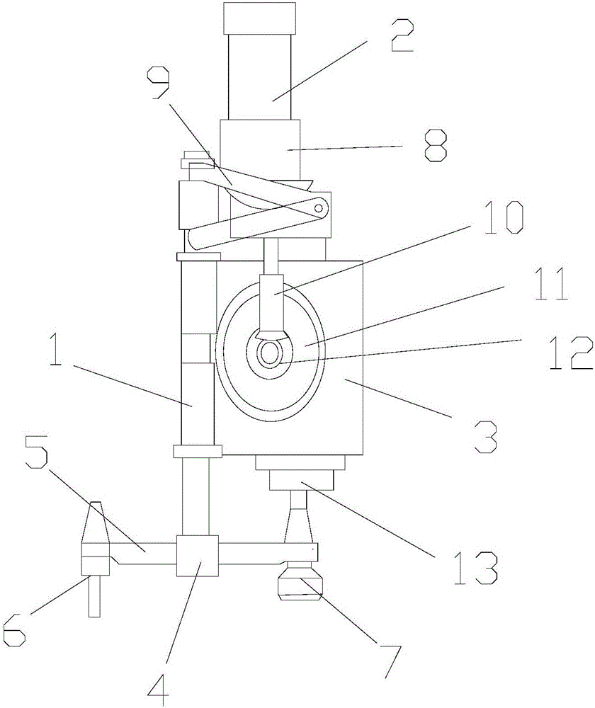
[0027] Such as figure 1 As shown, a tool changing device for a machine tool includes a main shaft 1, a drive motor 2 and a drive box 3. The main shaft 1 is located on the left side of the drive box 3 and is fixed with the drive box 3. The lower end of the main shaft 1 is arranged There is a barge joint 4, the two ends of the barge joint 4 are provided with jaws 5, the jaw 5 on the left side is provided with a spare tool 6, the jaw 5 on the right side is provided with a tool 7, and the drive motor 2 is located above the driving box 3, the lower end of the driving motor 2 is provided with a connecting seat 8, the connecting seat 8 is fixed with the driving box 3, the connecting seat 8 is provided with a movable rod 9, and the connecting seat 8 The lower end of the drive shaft 10 is provided with a drive shaft 10, the drive shaft 10 is located in the drive box 3, the drive box 3 is provided with a reduction wheel 11, the reduction wheel 11 is provided with a meshing gear 12, the ...

Embodiment 2

[0046] Such as figure 1As shown, a tool changing device for a machine tool includes a main shaft 1, a drive motor 2 and a drive box 3. The main shaft 1 is located on the left side of the drive box 3 and is fixed with the drive box 3. The lower end of the main shaft 1 is arranged There is a barge joint 4, the two ends of the barge joint 4 are provided with jaws 5, the jaw 5 on the left side is provided with a spare tool 6, the jaw 5 on the right side is provided with a tool 7, and the drive motor 2 is located above the driving box 3, the lower end of the driving motor 2 is provided with a connecting seat 8, the connecting seat 8 is fixed with the driving box 3, the connecting seat 8 is provided with a movable rod 9, and the connecting seat 8 The lower end of the drive shaft 10 is provided with a drive shaft 10, the drive shaft 10 is located in the drive box 3, the drive box 3 is provided with a reduction wheel 11, the reduction wheel 11 is provided with a meshing gear 12, the l...

Embodiment 3

[0065] Such as figure 1 As shown, a tool changing device for a machine tool includes a main shaft 1, a drive motor 2 and a drive box 3. The main shaft 1 is located on the left side of the drive box 3 and is fixed with the drive box 3. The lower end of the main shaft 1 is arranged There is a barge joint 4, the two ends of the barge joint 4 are provided with jaws 5, the jaw 5 on the left side is provided with a spare tool 6, the jaw 5 on the right side is provided with a tool 7, and the drive motor 2 is located above the driving box 3, the lower end of the driving motor 2 is provided with a connecting seat 8, the connecting seat 8 is fixed with the driving box 3, the connecting seat 8 is provided with a movable rod 9, and the connecting seat 8 The lower end of the drive shaft 10 is provided with a drive shaft 10, the drive shaft 10 is located in the drive box 3, the drive box 3 is provided with a reduction wheel 11, the reduction wheel 11 is provided with a meshing gear 12, the ...


PUM


Abstract

The invention discloses a tool changing device for a machine tool. The tool changing device comprises a main shaft, a driving motor and a driving box, wherein the main shaft is positioned on the left side of the driving box and is fixed to the driving box, a connecting head is arranged on the lower end of the main shaft, clamping jaws are arranged on both ends of the connecting head, a standby tool is arranged on the left clamping jaw, a tool is arranged on the right clamping jaw, the driving motor is positioned above the driving box, a connecting seat is arranged on the lower end of the driving motor, the connecting seat is fixed to the driving box, a movable rod is arranged on the connecting seat, a driving shaft is arranged on the lower end of the connecting seat, the driving shaft is positioned in the driving box, a speed reduction wheel is arranged in the driving box, a meshing gear is arranged in the speed reduction wheel, and a drill is arranged on the lower end of the driving box. The tool changing device for the machine tool has the advantages of convenience and rapidity in tool changing, high efficiency and convenience in control, and the main shaft has the advantages of high hardness and good toughness.

Description

technical field [0001] The invention relates to a tool changing device for a machine tool. Background technique [0002] At present, most of the tool changes in the existing machining center disc tool magazines have been automated. Automatic tool replacement is realized through pre-designed control system combined with mechanical structure. In the automatic tool change, the control system and structure in order to prevent the collision between the tool change axis and the tool magazine manipulator are not well designed and perfect. Once the automatic tool change multi-stage operation stops abnormally in the middle, the movement axis will often hit the robot arm. The phenomenon of damage to the tool magazine occurs, causing huge losses. [0003] In addition, the existing tool changing devices for machine tools are difficult to change, low in efficiency and inconvenient to control, and most of the existing spindles are low in hardness, fragile and easy to break, and low in t...

Claims


Application Information

Patent Timeline
IPC IPC(8): B23Q3/157C22C33/00B23P15/14
CPCB23Q3/15713B23P15/14C22C33/006
Inventor 肖双民吴杰锋王凯张卫卫胡泽睿
Owner NINGBO JINKAI MASCH TOOL CO LTD
Why Eureka
Try Eureka