Automatic feeding and discharging mechanical device
A technology of automatic loading and unloading and mechanical devices, applied in metal processing and other directions, can solve the problems of inability to form flexible manufacturing units, low integration, and lower competitiveness of enterprises, and achieve the effect of simple and effective integration
- Summary
- Abstract
- Description
- Claims
- Application Information
AI Technical Summary
Problems solved by technology
Method used
Image
Examples
Embodiment 1
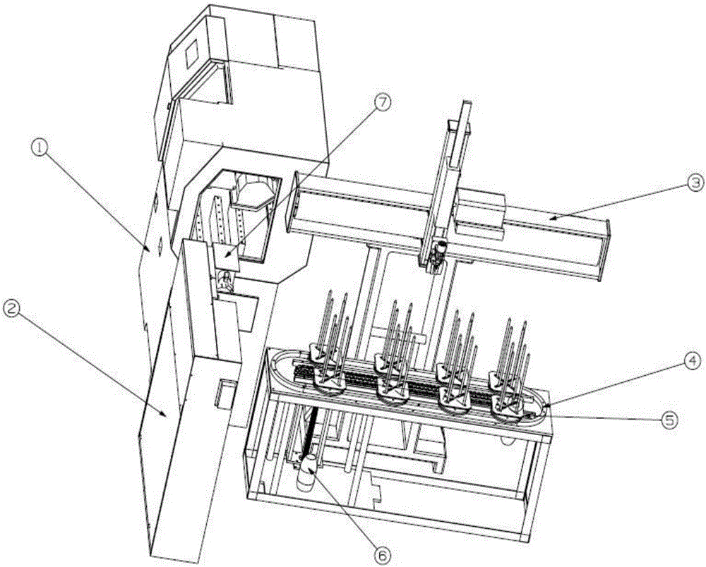
[0107] Such as figure 1 As shown, the present invention discloses an automatic loading and unloading mechanical device, which is applied to a CNC lathe 1, including a built-in manipulator 2 and a feeding manipulator 3, wherein:
[0108] The replenishing manipulator 3 includes a vertical movement mechanism and a horizontal movement mechanism that are vertically connected to each other, and the vertical movement mechanism is used to move up and down and from the upper tray 5 of the material table 4 at the front end of the replenishment manipulator 3 Clamp the workpiece to be processed, and translate the workpiece to be processed to the 2 built-in manipulators through the horizontal motion mechanism;
[0109] The built-in manipulator 2 and the replenishing manipulator 3 are arranged perpendicular to each other, and are used to grip and translate the workpiece to be processed to the built-in manipulator 3 and transfer it to the CNC lathe 1 for processing.
[0110] In the present ...
Embodiment 2
[0127] The present invention additionally discloses an automatic loading and unloading method, which is applied to a numerically controlled lathe. When there is no workpiece on the numerically controlled lathe, the steps are as follows:
[0128] Step A1: Manipulator to the first station
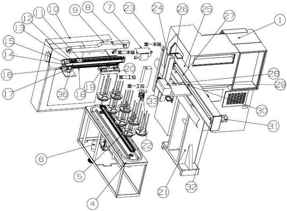
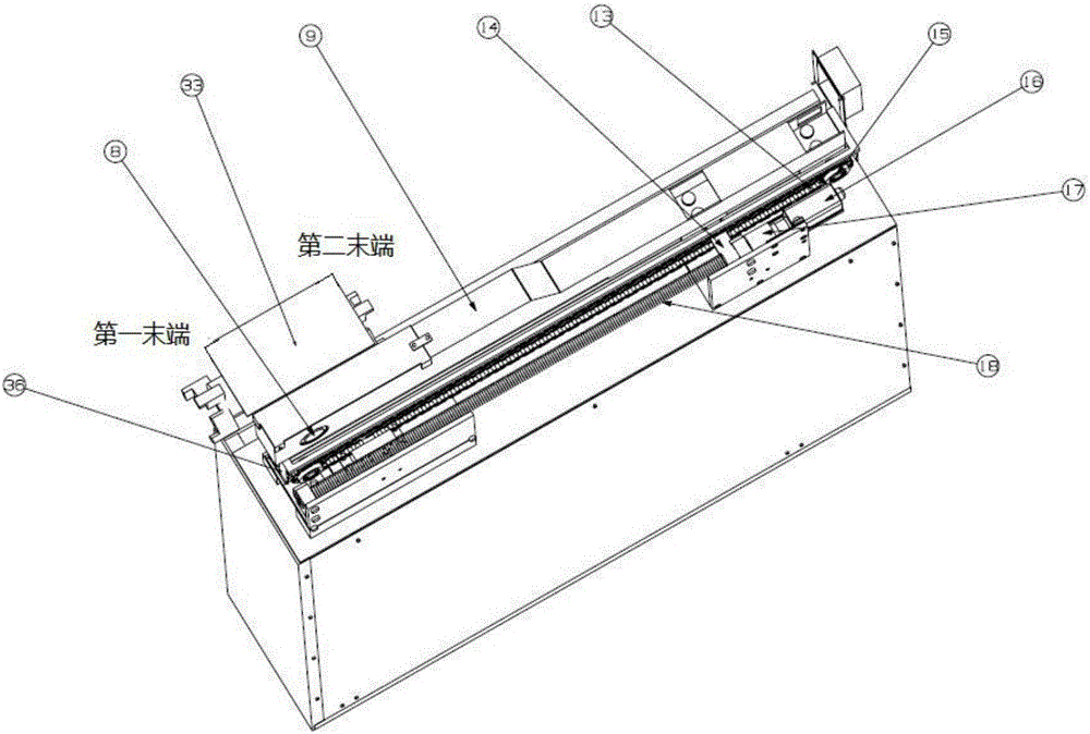
[0129] The feeding manipulator drive motor 31 drives the flexible belt 27 to move through the gear 26, the flexible belt 27 and the translation frame 24 are connected by a pulley (not marked in the figure), and the pulley and the feeding slide block 29 are connected by a slide block 30, When the feeding manipulator drive motor 31 is started, it can drive the sliding block 30 to realize translation, and the translation frame 24 and the sliding block 30 are connected by bolts. Thereby can realize the parallel movement of translation frame 24, drive the motion of rack and pinion mechanism 33, servo motor 28, manipulator 22 etc., manipulator 22 is moved to the top of the first station accurately,...
Embodiment 3
[0153] The invention also discloses an automatic loading and unloading method, which is applied to a numerically controlled lathe. When there are workpieces on the numerically controlled lathe, the steps are as follows:
[0154] Step B1: Manipulator to the second station
[0155] The feeding manipulator drive motor 31 drives the flexible belt 27 to move through the gear 26, the flexible belt 27 is connected with the translation frame 24 through a pulley, and the belt pulley is connected with the feeding slider 29 through a sliding block 30, when the feeding manipulator drive motor After the 31 starts, it can drive the sliding block 30 to realize translation, and the translation frame 24 and the sliding block 30 are connected by bolts. Thereby can realize the parallel movement of translation frame 24, drive the motion of rack and pinion mechanism 33, servo motor 28, manipulator 22 etc., manipulator 22 is accurately moved to the top of the second station, then servo motor 28 sta...
PUM
 Abstract
Description
Claims
Application Information
 - R&D
- Intellectual Property
- Life Sciences
- Materials
- Tech Scout
- Unparalleled Data Quality
- Higher Quality Content
- 60% Fewer Hallucinations
Browse by: Latest US Patents, China's latest patents, Technical Efficacy Thesaurus, Application Domain, Technology Topic, Popular Technical Reports.
© 2025 PatSnap. All rights reserved.Legal|Privacy policy|Modern Slavery Act Transparency Statement|Sitemap|About US| Contact US: help@patsnap.com


