Yarn conveying and winding mechanism

A winding mechanism and yarn technology, applied in the direction of conveying filamentous materials, thin material handling, transportation and packaging, etc., can solve problems such as complex operations, troubles, reducing the efficiency and quality of yarn roll transmission and winding, and achieve improved Efficiency and quality, the effect of simple structure

Inactive Publication Date: 2016-11-09
ZHEJIANG ZHONGSHI MACHINERY CO LTD
View PDF9 Cites 8 Cited by
  • Summary
  • Abstract
  • Description
  • Claims
  • Application Information

AI Technical Summary

Problems solved by technology

[0002] Because of its good moisture absorption and air permeability, soft and comfortable to wear, and good warmth retention, the fabric has been widely used in our daily life, and the fabric has good dyeing performance, bright color, complete color spectrum, and strong alkali resistance. Heat and light resistance, especially warp-knitted fabrics, have good elongation and stretchability, and good dimensional stability. Need, it is necessary to use the winding mechanism to wind the small yarn rolls into relatively large yarn rolls, and then place the larger yarn rolls on the warp knitting machine, so that the service life of the yarn rolls can be improved, ensuring that the warp knitting machine weaves Excellent product stability, the existing yarn transmission and winding mechanism has complex structure and troublesome operation, it is difficult to quickly and efficiently transmit and wind the yarn, and the tension of the yarn transmission cannot be conveniently adjusted according to the needs during the yarn transmission process. Moreover, the size and specifications of the yarn winding cannot be adjusted according to the needs. The existing yarn winding mechanism cannot easily remove the yarn roll after the yarn winding is completed, and the yarn roll needs to be pulled to remove it from the roll. Take it off from the winding rod, which affects the quality of the yarn roll, reduces the efficiency and quality of the yarn roll transmission and winding, and cannot meet the needs of production and use.

Method used


Image

  • Yarn conveying and winding mechanism
  • Yarn conveying and winding mechanism

Examples


Embodiment Construction

[0011] In order to further describe the present invention, a specific implementation of a yarn transmission and winding mechanism will be further described below in conjunction with the accompanying drawings. The following examples are explanations of the present invention and the present invention is not limited to the following examples.

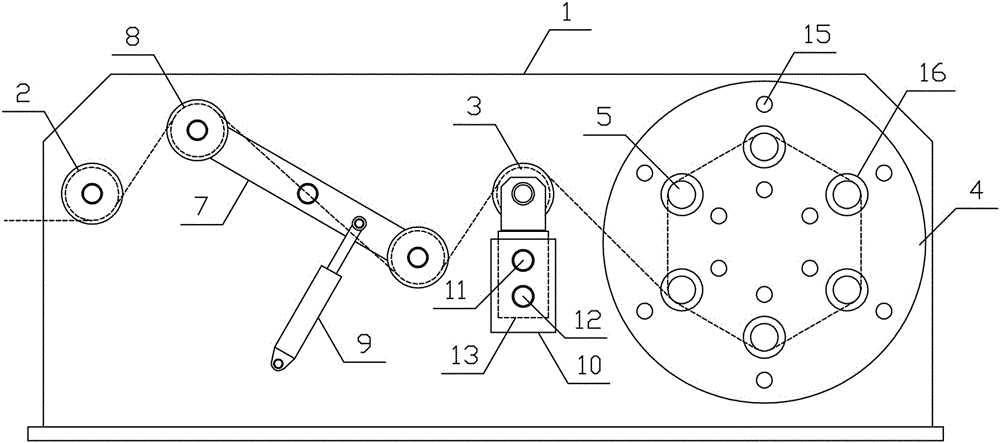
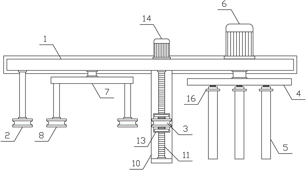
[0012] like figure 1 , figure 2 As shown, a yarn transmission and winding mechanism of the present invention includes a winding bracket 1, a wire feed wheel 2, a guide wheel 3, a yarn adjustment mechanism, a rotating circular plate 4, a winding rod 5 and a winding motor 6, and The wire wheel 2, the yarn adjusting mechanism and the guide wheel 3 are arranged in sequence along the yarn conveying direction, the wire feeding wheel 2 is vertically rotatably connected to the winding support 1, and the yarn adjusting mechanism includes a rotating adjusting plate 7, an adjusting wheel 8 and a rotating hydraulic pressure Cylinder 9, the middle pa...


PUM


Abstract

The invention discloses a yarn conveying and winding mechanism and belongs to the field of textile processing machinery and equipment. The yarn conveying and winding mechanism comprises a winding bracket, a yarn feeding wheel, a yarn guide wheel, a yarn adjusting mechanism, a rotary circular plate, winding rods and a winding motor, wherein the yarn feeding wheel is vertically and rotatably connected with the winding bracket; the yarn adjusting mechanism comprises a rotary adjusting plate, adjusting wheels and a rotary hydraulic cylinder; two ends of the rotary adjusting plate are respectively, vertically and rotatably connected with the adjusting wheels; the rotary hydraulic cylinder is arranged between the rotary adjusting plate and the winding bracket; a translation screw rod is in threaded connection with a translation plate; the yarn guide wheel is vertically and rotatably connected with the upper side of the translation plate; and a translation motor drives the translation screw rod, the winding motor drives the rotary circular plate, and one side of the rotary circular plate is horizontally and uniformly provided with multiple winding rods. The yarn conveying and winding mechanism is reasonable in structural design, is capable of quickly, efficiently, uniformly and orderly conveying and winding yarns, and meets the demands of production and use.

Description

technical field [0001] The invention belongs to the field of textile processing machinery, in particular to a yarn transmission and winding mechanism. Background technique [0002] Because of its good moisture absorption and air permeability, soft and comfortable to wear, and good warmth retention, the fabric has been widely used in our daily life, and the fabric has good dyeing performance, bright color, complete color spectrum, and strong alkali resistance. Heat and light resistance, especially warp-knitted fabrics, have good elongation and stretchability, and good dimensional stability. Need, it is necessary to use the winding mechanism to wind the small yarn rolls into relatively large yarn rolls, and then place the larger yarn rolls on the warp knitting machine, so that the service life of the yarn rolls can be improved, ensuring that the warp knitting machine weaves Excellent product stability, the existing yarn transmission and winding mechanism has complex structure...

Claims


Application Information

Patent Timeline
Patent Type & Authority Applications(China)
IPC IPC(8): B65H54/02B65H54/30B65H54/547B65H59/10
CPCB65H54/02B65H54/30B65H54/547B65H59/10B65H2701/31
Inventor 单利明
Owner ZHEJIANG ZHONGSHI MACHINERY CO LTD
Why Eureka
Try Eureka