
Uniform feeding cotton condensing device

A technology for condensing and feeding materials, which is applied to the field of uniform feeding and condensing devices, can solve the problems of affecting the effect of thugs stripping cotton, uneven quality of cotton laps, and unequal raw materials, so as to eliminate hidden dangers of fire accidents, avoid fires, and make it difficult to wear effect

Inactive Publication Date: 2016-11-09
GUANGDE TIANYUN NEW TECH
View PDF7 Cites 5 Cited by
  • Summary
  • Abstract
  • Description
  • Claims
  • Application Information

AI Technical Summary

Problems solved by technology

The existing condenser is fixed on the frame by the flange plate, and the rubber pad is installed on the flange plate. When the condensate dust cage rotates, friction occurs between the two, and the rubber pad is damaged, and the rubber pad is damaged. Cotton is easy to accumulate in the gap, and even cause a fire due to friction and heat; in addition, simply using the condensate dust cage and fan to cooperate with the impurity removal effect is not good; The thickness of the raw materials adsorbed on the outer surface of the cotton dust cage is relatively thick, which causes the left and right raw materials inside the frame to be uneven, and the quality of the produced cotton laps is uneven, which affects the product quality; It is easy to cause the equipment to choke and stop

Method used


Image

  • Uniform feeding cotton condensing device
  • Uniform feeding cotton condensing device
  • Uniform feeding cotton condensing device

Examples


Embodiment Construction

[0016] The technical solutions in the embodiments of the present invention will be clearly and completely described below in conjunction with the accompanying drawings in the embodiments of the present invention. Obviously, the described embodiments are only a part of the embodiments of the present invention, rather than all the embodiments. Based on the embodiments of the present invention, all other embodiments obtained by those of ordinary skill in the art without creative work shall fall within the protection scope of the present invention.

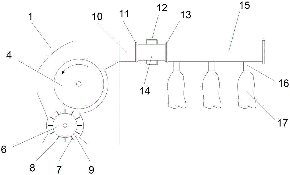
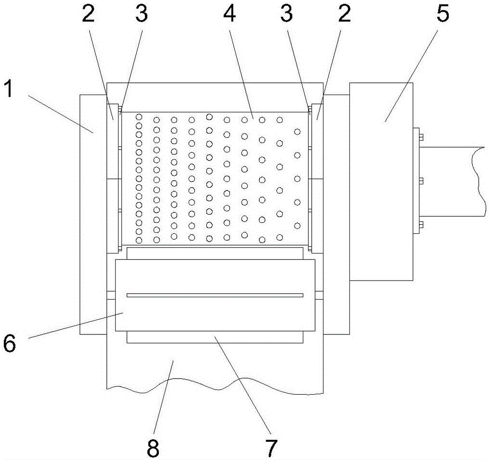
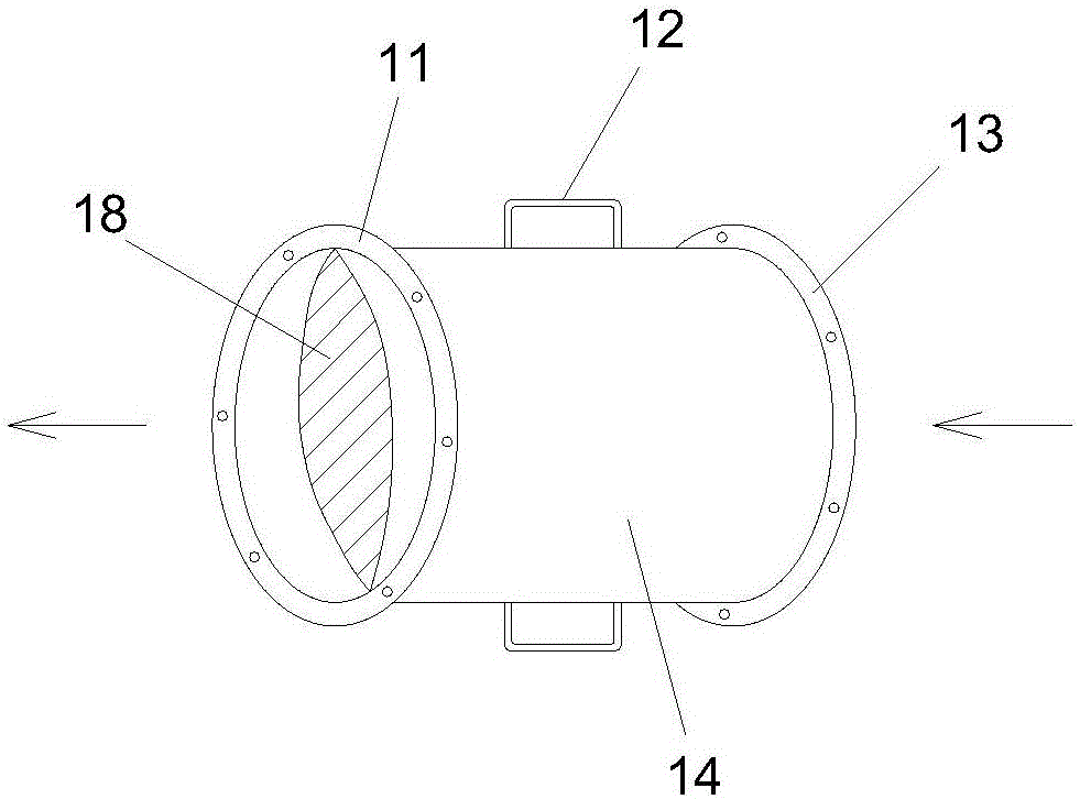
[0017] See Figure 1~3 In the embodiment of the present invention, a uniform feeding and condensing device includes a frame 1, a condensing dust cage 4, a cotton stripper 6 and a fan 5. The two ends of the condensing dust cage 4 are buckled with arc wood rings 2 , The condensed cotton dust cage 4 is fixed on the frame 1 through the arc wood rings 2 at both ends. The inner ring surface of the arc wood ring 2 is provided with a sealing fel...


PUM


Abstract

The invention discloses a uniform feeding cotton condensing device which comprises a machine frame, a cotton condensing dust cage, a cotton stripping beating hand and a fan. Arc-shaped wood rings are buckled at the two ends of the cotton condensing dust cage, the cotton condensing dust cage is fixed to the machine frame through the arc-shaped wood rings at the two ends, and the inner ring surfaces of the arc-shaped wood rings are provided with sealing felt pads. The sealing felt pads press the ends of the two sides of the outer surface of the cotton condensing dust cage, and the cotton stripping beating hand is installed on the machine frame positioned below the cotton condensing dust cage. The cotton stripping beating hand is composed of a cotton stripping roller and a cotton scraping plate evenly installed on the cotton stripping roller. The machine frame below the cotton stripping beating hand is provided with a discharging port, the right side of the cotton condensing dust cage is connected with the fan, the outer surface of the cotton condensing dust cage is provided with a plurality of suction holes, and the number of the suction holes is sequentially increased from right to left in the length direction of the cotton condensing dust cage. The upper portion of the machine frame is provided with a cotton inlet, and the cotton inlet is connected with an adjusting channel. The uniform feeding cotton condensing device is simple in structure and good in dedusting effect, raw materials are adsorbed evenly, the discharge quality is high, and fires caused by heat generated by friction are avoided.

Description

Technical field [0001] The invention relates to the technical field of mechanical processing, in particular to a uniform feeding and coagulation device. Background technique [0002] Condenser is a clearing equipment in the cotton spinning industry, and its function is to remove dust and lint in the cotton. The main components of the condensing device include the driving part, the fan part, the condensing dust cage part and the cotton stripping beater part. Its working principle is: when the fan rotates at high speed, negative pressure is formed in the condensing dust cage, the cotton tufts entering the condensing device are condensed on the surface of the rotating condensing dust cage, and the airflow carries dust and lint through the condensing cotton. The holes on the dust cage enter the inside of the condensed cotton dust cage and are discharged to the dust filter device through the fan impeller. During the rotating process of the condensed cotton dust cage, the cotton tuft...

Claims


Application Information

Patent Timeline
IPC IPC(8): D01G9/08D01G9/14
CPCD01G9/08D01G9/14
Inventor 潘建新张陆贤
Owner GUANGDE TIANYUN NEW TECH
Learn More