compressor
A compressor and compression mechanism technology, applied in the field of compressors, can solve problems affecting the performance of air conditioning systems, adverse effects of heat exchangers, etc., and achieve the effects of high energy efficiency, small oil discharge, and reduced oil discharge
- Summary
- Abstract
- Description
- Claims
- Application Information
AI Technical Summary
Problems solved by technology
Method used
Image
Examples
Embodiment 1
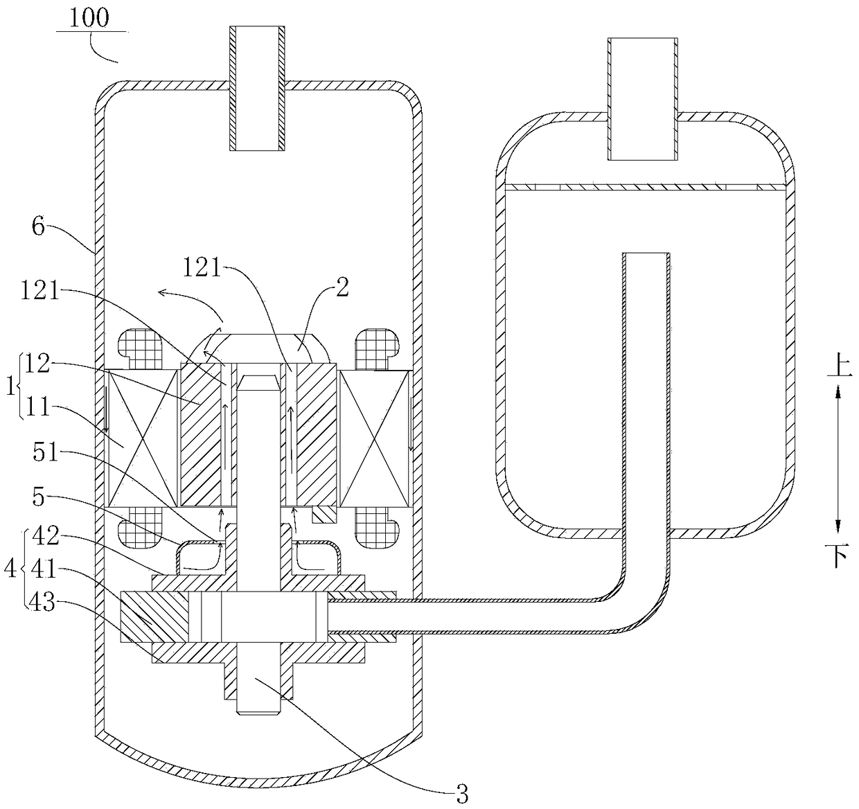
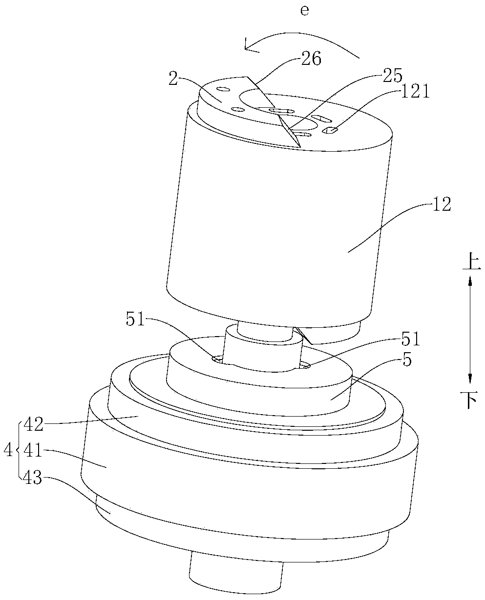
[0074] Such as Figure 1-Figure 7 , Figure 10 and Figure 11 As shown, the compressor 100 according to the embodiment of the present invention includes a motor 1 , a crankshaft 3 , a compression mechanism 4 , a muffler cover 5 and a casing 6 .
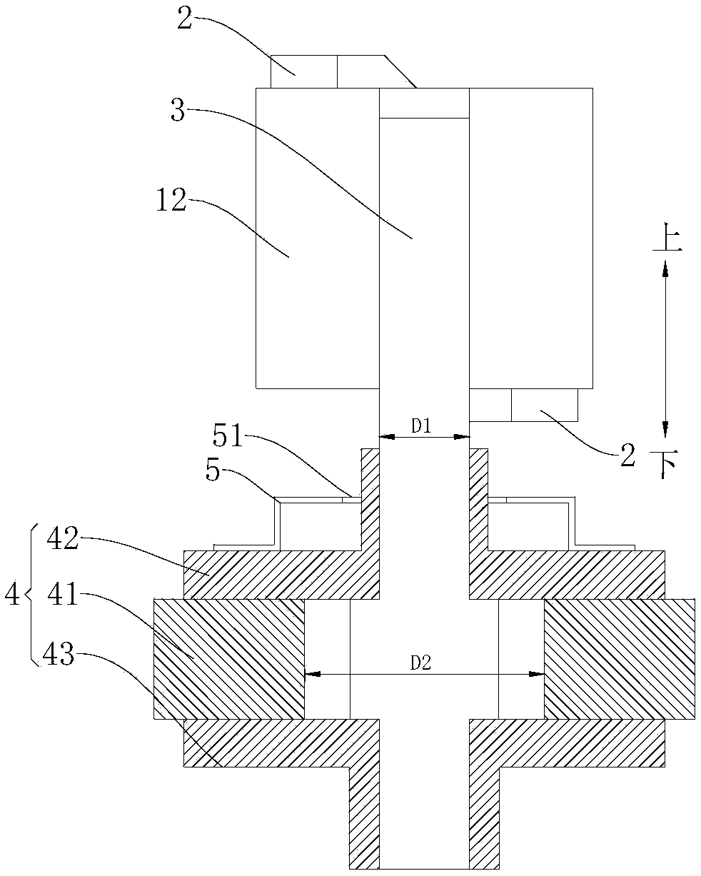
[0075] Specifically, such as figure 1 As shown, the motor 1 includes a stator 11 and a rotor 12 , the stator 11 is sheathed on the rotor 12 , the rotor 12 is provided with an exhaust channel 121 penetrating up and down, and the upper end surface of the rotor 12 is provided with a balance weight 2 . The upper end of the crankshaft 3 is connected to the rotor 12 , and the exhaust passage 121 is arranged close to the crankshaft 3 . The muffler cover 5 covers the upper end face of the compression mechanism 4, and the crankshaft 3 passes through the muffler cover 5 and is connected with the compression mechanism 4, wherein the compression mechanism 4 includes an upper bearing 42, a lower bearing 43 and a cylinder 41, and the cylinder 41...
Embodiment 2
[0080] Such as Figure 1-Figure 4 , Figure 8 , Figure 10 and Figure 11 As shown, the structure of this embodiment is substantially the same as that of Embodiment 1, wherein the same components use the same reference numerals, the only difference is that in this embodiment, the sound absorbing cover 5 is provided with a vent hole 51, and the crankshaft 3 Through the air hole 51, the diameter of the crankshaft 3 is D1, and the diameter of the air hole 51 is D4, and D1 and D4 satisfy D4>D1. This can ensure that the refrigerant airflow discharged from the muffler cover 5 is discharged into the exhaust passage 121 through the gap between the vent hole 51 and the crankshaft 3, and flows upward to the space above the rotor 12, effectively reducing the space between the stator 11 and the crankshaft 3. The amount of refrigerant flowing upward through the gap between the housings 6 enables the lubricating oil to flow back to the lower space of the motor 1 through the gap between t...
Embodiment 3
[0082] Such as Figure 1-Figure 4 , Figure 9-Figure 11 As shown, the structure of this embodiment is substantially the same as that of the second embodiment, wherein the same components use the same reference numerals, the only difference is that in this embodiment, a guide ring 52 is provided at the vent hole 51, The guide ring 52 is located above the muffler cover 5 and extends along the circumferential direction of the vent hole 51 . The deflector ring 52 can play a certain guiding role, and can make the refrigerant flow flowing out from the gap between the inner peripheral wall of the vent hole 51 and the outer peripheral wall of the crankshaft 3 smoothly flow into the exhaust passage 121 on the rotor 12, and Flowing to the upper space of the motor 1 effectively reduces the amount of refrigerant flowing upward in the gap between the stator 11 and the housing 6, so that the lubricating oil can smoothly flow back to the lower space of the motor 1 through the gap between th...
PUM
 Abstract
Description
Claims
Application Information
 - R&D
- Intellectual Property
- Life Sciences
- Materials
- Tech Scout
- Unparalleled Data Quality
- Higher Quality Content
- 60% Fewer Hallucinations
Browse by: Latest US Patents, China's latest patents, Technical Efficacy Thesaurus, Application Domain, Technology Topic, Popular Technical Reports.
© 2025 PatSnap. All rights reserved.Legal|Privacy policy|Modern Slavery Act Transparency Statement|Sitemap|About US| Contact US: help@patsnap.com


