
High-power pressure reducing valve of pipeline

A high-power, pressure-reducing valve technology, applied in the direction of functional valves, safety valves, balance valves, etc., can solve problems such as insufficient transmission stability, complex structure, and poor pressure regulation accuracy, and achieve simple structure, good safety performance, The effect of long service life

Inactive Publication Date: 2016-11-09
虞上海
View PDF5 Cites 0 Cited by
  • Summary
  • Abstract
  • Description
  • Claims
  • Application Information

AI Technical Summary

Problems solved by technology

[0003] However, its structure is complex, the transmission is not stable enough, and the precision of regulating pressure is not good.

Method used


Image

  • High-power pressure reducing valve of pipeline
  • High-power pressure reducing valve of pipeline
  • High-power pressure reducing valve of pipeline

Examples


Embodiment Construction

[0026] Embodiments of the present invention are described in detail below, examples of which are shown in the drawings, wherein the same or similar reference numerals represent the same or similar elements or elements having the same or similar functions throughout.

[0027] In the description of the present invention, it should be noted that for orientation words, such as the term "center", "horizontal", "longitudinal", "length", "width", "thickness", "upper", "lower" , "Front", "Back", "Left", "Right", "Vertical", "Horizontal", "Top", "Bottom", "Inner", "Outer", "Clockwise", "Counterclockwise " and other indication orientations and positional relationships are based on the orientations or positional relationships shown in the drawings, and are only for the convenience of describing the present invention and simplifying the description, rather than indicating or implying that the device or element referred to must have a specific orientation, or in a specific orientation. The...


PUM


Abstract

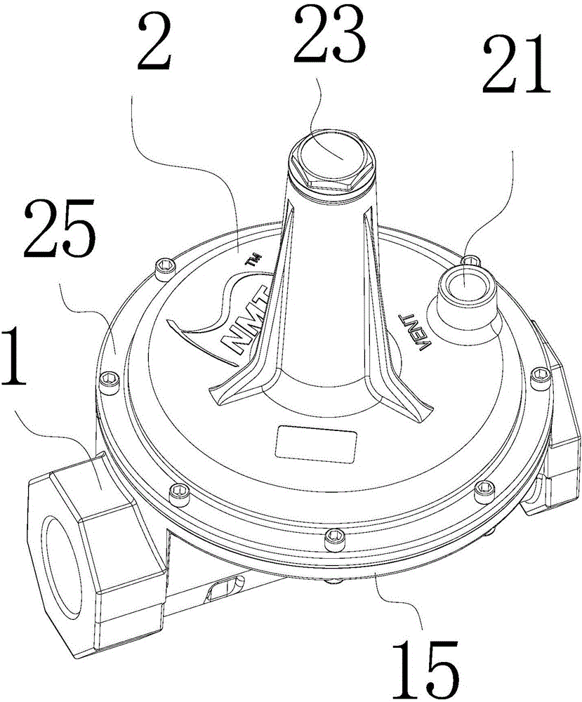
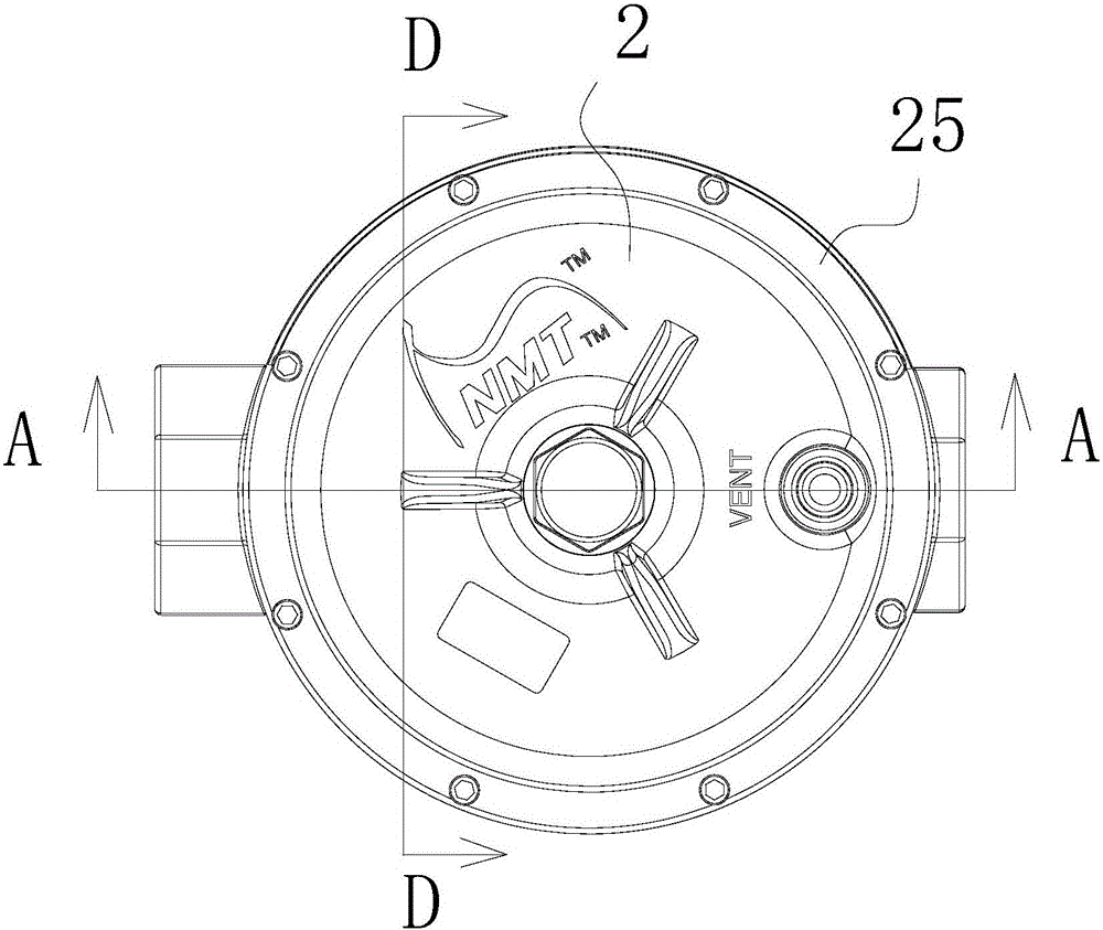
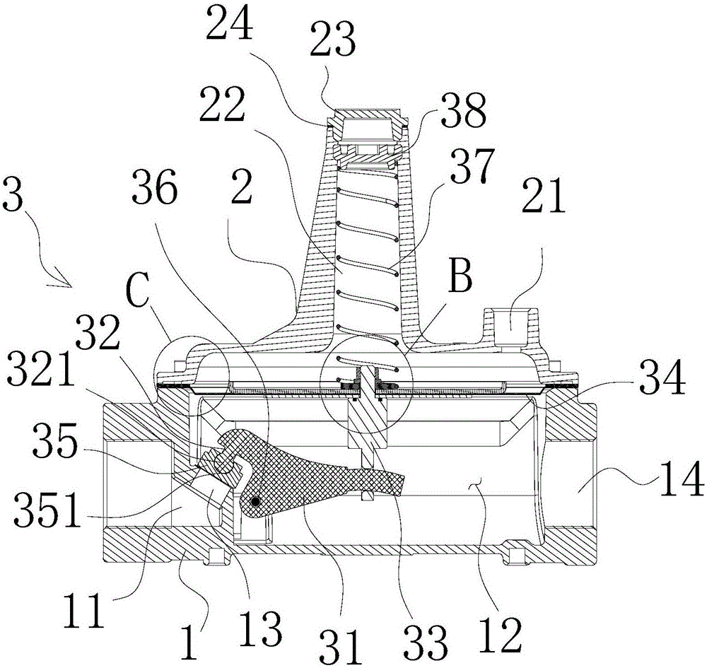
A high-power pressure reducing valve of a pipeline comprises a valve seat, a valve deck combined on the valve seat and a pressure regulating actuating mechanism, wherein the valve deck is provided with an air release opening; an air inlet chamber and an air regulating chamber are arranged inside the valve seat; an air inlet channel is arranged between the air inlet chamber and the air regulating chamber; the pressure regulating actuating mechanism comprises a movable warping plate pivoted to the valve seat; one end of the movable warping plate is connected with a valve rod; the other end of the movable warping plate is connected with a movable piece; the movable piece is connected with a flexible membrane; the flexible membrane responds to the intake pressure changes so as to drive the movable piece; the valve rod is provided with a valve element portion used for being in movable fit with an intake channel so as to change the opening of the intake channel; the flexible membrane drives the movable piece to act vertically under the air pressure changes; and the movable warping plate bounces through the movable piece so as to swing around a pin shaft, and accordingly the valve element portion drives the volume of the pressure regulating chamber to change relative to the size changes of the opening of the intake channel. The high-power reducing valve of the pipeline is simple in structure, good in safety performance, low in manufacturing cost, stable in driving, long in service life and stable in pressure regulation.

Description

【Technical field】 [0001] The invention relates to a pipeline high-power pressure reducing valve. 【Background technique】 [0002] According to market research, in our daily life, pipeline natural gas and liquefied petroleum gas are necessities that we cannot live without, but they are also dangerous goods. The country has strict installation requirements for pipeline natural gas and liquefied petroleum gas. The main requirements are two aspects: one is good sealing performance and no leakage; Every community and every household has to go through layers of decompression to achieve safe use. At present, there are many pressure reducing valves on the market, but domestic manufacturers of professional valves for high-power pressure reducing valves for pipelines are still blank, and all rely on imports from Japan and the United States. The pressure reducing valves used by Towngas China Gas and CNOOC Pipeline Gas in Zhongshan City are all imported from abroad. Moreover, the pric...

Claims


Application Information

Patent Timeline
Patent Type & Authority Applications(China)
IPC IPC(8): F16K17/30
CPCF16K17/30
Inventor 虞上海牛人田
Owner 虞上海
Learn More