Check joint for discharging chemicals
A chemical, non-return technology, applied in the direction of pipes/pipe joints/fittings, connections with fluid cut-off devices, parts in contact between valve elements and valve seats, etc., can solve the problem of damage to corrosion-resistant elastic materials, contamination of chemical Products, unsuitable for high-purity electronic chemicals, etc., to simplify the structure and reduce the chance of contamination
- Summary
- Abstract
- Description
- Claims
- Application Information
AI Technical Summary
Problems solved by technology
Method used
Image
Examples
Embodiment 1
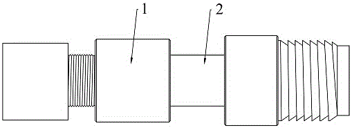
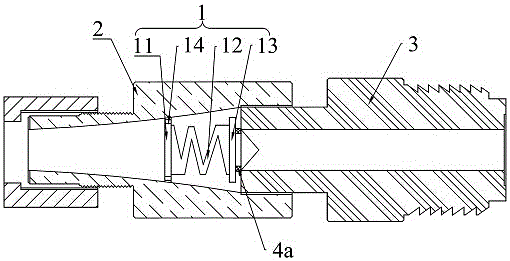
[0028] Such as figure 1 with 2 As shown, the chemical discharge check joint of embodiment 1 includes a check valve core 1 made of polymer material and a first joint 2 and a second joint 3 with a central through hole, and the discharge end of the second joint 3 Socketed in the feed end of the first joint 2 and sealed connected, the hole diameter of the discharge port of the first joint 2 is smaller than that of the feed port, and the inner surface of the first joint 2 and the discharge end surface of the second joint 3 form a cavity A check valve core 1 is arranged in the middle clearance, and the check valve core 1 includes a first baffle plate 11, a polymer material pressure spring 12 and a second baffle plate 13 connected in sequence, and the first baffle plate 11 is directed toward the first joint 2. A discharge hole 14 is arranged between the material end and the inner surface of the first joint 2, the second baffle plate 13 faces the discharge end of the second joint 3, ...
Embodiment 2
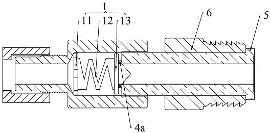
[0037] Such as image 3 As shown, the difference between Embodiment 2 and Embodiment 1 is that the feeding end of the second joint 3 is provided with a flange 5 protruding to the outer periphery, and the outer periphery of the second joint 3 is provided with a movable joint 6 in a clearance fit sleeve, and the movable joint 6 is located on the protrusion. Between the edge 5 and the first joint 3, the movable joint 6 is used to connect with the chemical discharge pipe or the packaging drum.
[0038] The surface of the second baffle 13 is provided with a guide block 7, the first sealing ring 4a is sheathed on the outer periphery of the guide block 7, and the protruding end of the guide block 7 matches with the discharge port of the second joint.
[0039] A lug 9 is provided on the top or side of the first baffle 11 , and the discharge hole is enclosed by the lug 9 , the first baffle 11 and the inner surface of the first joint 2 .
[0040] The central through hole of the first c...
Embodiment 3
[0043] Such as Figure 4 As shown, the difference between Embodiment 3 and Embodiment 2 is that a protruding ring 10 is provided on the outer surface of the second joint 3, and a second sealing ring 4b is provided on the ring surface of the protruding ring 10 facing the feeding end face of the first joint 2, The second sealing ring 4b is interposed between the protruding ring 10 and the feed end surface of the first joint 2 .
[0044] The ratio of the wire diameter of the compression spring to the inner diameter and pitch of the compression spring is 1:7:2, and the model of the polymer material is polyvinylidene fluoride is Kynar PVDF 100HD.
[0045] When the ratio of the wire diameter of the compression spring to the inner diameter of the compression spring is less than 1:8 and the pitch is less than 1:3, the deformation force of the compression spring is small, the flexibility of the spring is too large, and the rigidity is insufficient. When the ratio of the wire diameter ...
PUM
 Abstract
Description
Claims
Application Information
 - R&D
- Intellectual Property
- Life Sciences
- Materials
- Tech Scout
- Unparalleled Data Quality
- Higher Quality Content
- 60% Fewer Hallucinations
Browse by: Latest US Patents, China's latest patents, Technical Efficacy Thesaurus, Application Domain, Technology Topic, Popular Technical Reports.
© 2025 PatSnap. All rights reserved.Legal|Privacy policy|Modern Slavery Act Transparency Statement|Sitemap|About US| Contact US: help@patsnap.com


