
Energy saving control method for constant temperature water supply and fixed frequency heat pump hot water heating system

A technology for heat pump hot water and heating systems, which is applied in heating systems, heat recovery systems, space heating and ventilation details, etc. It can solve the problems of large differences in thermal insulation performance, heat exchange coil laying, temperature stability in heating rooms, Different groups of people have different temperature senses, achieving obvious energy-saving effects, accurate calculation of water supply temperature, and constant water supply temperature

Active Publication Date: 2018-05-29
SHUNDE POLYTECHNIC
View PDF6 Cites 0 Cited by
  • Summary
  • Abstract
  • Description
  • Claims
  • Application Information

AI Technical Summary

Problems solved by technology

However, due to the dynamic changes in the outdoor ambient temperature, the thermal insulation performance of different buildings and the laying of heat exchange coils are quite different, and the temperature perception of different groups of people is different, how to use a simple method to determine the optimal heat pump water supply temperature is to achieve heat pump operation The key to energy saving
At the same time, since the fixed-frequency heat pump adopts on-off control to control the water supply temperature, the water supply temperature fluctuates greatly, which has a certain impact on the temperature stability of the heating room. Therefore, it is also necessary to consider how to realize the stability of the water supply temperature in the system.

Method used


Image

  • Energy saving control method for constant temperature water supply and fixed frequency heat pump hot water heating system

Examples


Embodiment Construction

[0018] Embodiments of the invention are described in detail below, examples of which are illustrated in the accompanying drawings. The embodiments described below by referring to the figures are exemplary only for explaining the present invention and should not be construed as limiting the present invention.

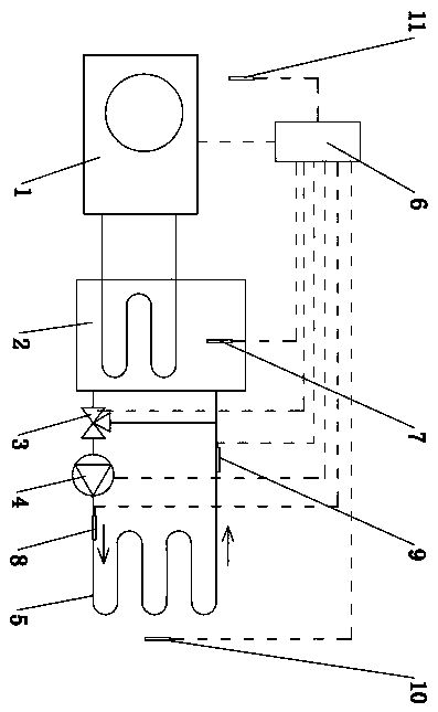
[0019] Such as figure 1 As shown, it is an energy-saving control method for a constant-temperature water supply and fixed-frequency heat pump hot water heating system. The fixed-frequency heat pump hot water heating system includes a fixed-frequency heat pump water heater 1, a water storage tank 2, a three-way proportional regulating valve 3, a circulating water pump 4, and a heat pump. Water coil 5, control system 6, water storage tank temperature sensor 7, water supply temperature sensor 8, return water temperature sensor 9, room air temperature sensor 10 and outdoor environment temperature sensor 11; wherein the water outlets of the hot water coil 5 are respectively ...


PUM


Abstract

The invention relates to an energy-saving control method for a constant-temperature water supply and fixed-frequency heat pump hot water heating system, which is characterized in that the steps of the energy-saving control method for the control system are as follows: establishing the temperature between the heat pump water supply calculation temperature Tgj, the indoor set temperature Tsd, and the outdoor environment temperature Tw The basic functional formula is to establish the first corrected functional formula for calculating the calculated water supply temperature Tgj of the heat pump, and establish the second corrected functional formula for calculating the calculated water supply temperature Tgj of the heat pump; by controlling the start and stop of the compressor of the fixed-frequency heat pump water heater, the actual water supply The temperature Tgs is 0~1℃ higher than the calculated water supply temperature Tgj obtained according to the second correction function formula; the control system adjusts the water supply and return water of the three-way proportional regulating valve by detecting the deviation between the actual water supply temperature Tgs and the water supply calculation temperature Tgj Ratio, so that the actual temperature Tgs of water supply and the calculated temperature Tgj of water supply tend to be consistent. Its advantages are: fully considering the differences in thermal insulation characteristics of different buildings and the laying of hot water coils, automatic judgment and correction during operation, more obvious energy saving effect, constant water supply temperature, and small room temperature fluctuations.

Description

technical field [0001] The invention relates to an energy-saving control method for a constant-temperature water supply and fixed-frequency heat pump hot water heating system. Background technique [0002] As a high-efficiency and energy-saving hot water product, heat pump water heaters are increasingly used in heating systems. At present, whether it is a fixed-frequency or fixed-frequency heat pump water heater floor heating system design, the water supply / return water temperature is generally 45°C / 35°C, and the room air temperature is mostly controlled by the floor surface temperature or room air temperature. The heat pump water heater is turned on and off. Because the energy efficiency of the heat pump water heater decreases with the increase of the water supply temperature, and the outdoor ambient temperature changes greatly within a heating cycle, and the outdoor ambient temperature also varies greatly within a day, therefore, its heating load in different time periods ...

Claims


Application Information

Patent Timeline
Patent Type & Authority Patents(China)
IPC IPC(8): F24D19/10F24D15/04
CPCY02B30/12Y02B30/52
Inventor 徐言生邹时智
Owner SHUNDE POLYTECHNIC
Learn More