Supercharge Your Innovation With Domain-Expert AI Agents!

Optical axis calibration system for laser range finder

A laser rangefinder and rangefinder technology, which is applied in the field of laser detection, can solve the problems of large experimental site area, large occupied area, and high cost, so as to reduce the cost of experimental equipment, reduce the axis adjustment site, and facilitate engineering production. Effect

Pending Publication Date: 2016-11-09
JIANGSU ZHONGKE DAGANG LASER TECH
View PDF2 Cites 1 Cited by
  • Summary
  • Abstract
  • Description
  • Claims
  • Application Information

AI Technical Summary

Problems solved by technology

[0004] One is to use a collimator with a large aperture and a long focal length for adjustment. The disadvantages are: 1) the cost is high, usually more than 100,000, 2) the instrument is bulky, at least 3 meters long, and occupies a large area;
[0005] One is to use an off-axis long focal length spherical mirror to adjust on the optical platform. The disadvantage is that an optical platform of about 4 meters is required, which occupies a larger area of ​​the experimental site. Although the cost is slightly lower than the former, it still needs about 100,000.

Method used


Image

  • Optical axis calibration system for laser range finder
  • Optical axis calibration system for laser range finder

Examples


Embodiment Construction

[0018] The preferred embodiments of the present invention will be described in detail below in conjunction with the accompanying drawings, so that the advantages and features of the present invention can be more easily understood by those skilled in the art, so as to define the protection scope of the present invention more clearly.

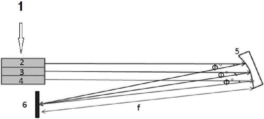
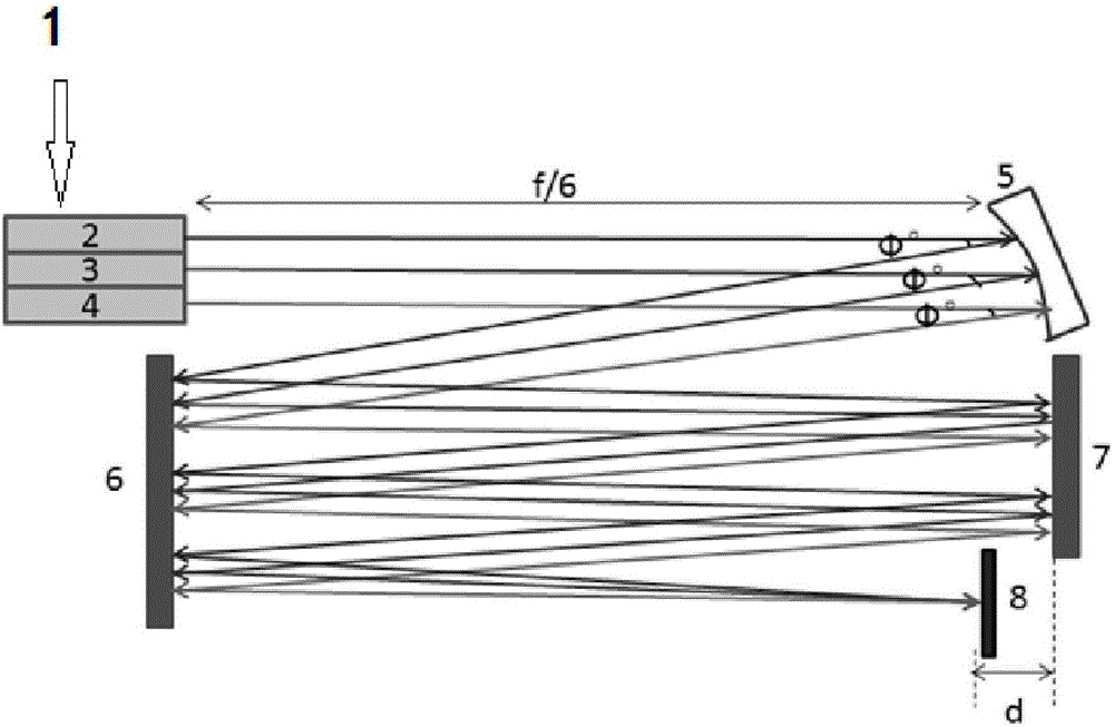
[0019] as attached figure 2 As shown in the figure, an optical axis adjustment system of a laser distance measuring machine is set on a horizontal platform as a whole when the system is working. figure 2 This is a top view of the system when it is placed on a horizontal platform.

[0020] It includes an aiming axis 2 , a transmitting axis 3 , a receiving axis 4 , a spherical focusing mirror 5 , a receiving screen 8 , a first plane mirror 6 , and a second plane mirror 7 issued by the rangefinder 1 . The spherical focusing mirror 5 is a large-diameter off-axis spherical mirror with a focal length of f, which is placed at an angle Φ with the vert...


PUM


Abstract

The invention discloses an optical axis calibration system for a laser range finder. The system comprises the range finder, an aiming axis, an emitting axis, a receiving axis, a spherical focus lens, a receiving screen, a first planar reflection mirror and a second planar reflection mirror, wherein the range finder emits the aiming axis, the emitting axis and the receiving axis. Optical axes emitted by the range finder pass through the spherical focus lens and then are reflected between the first planar reflection mirror and the second planar reflection mirror for many times and finally focused on the receiving screen. Compared with the prior art, the optical axis calibration system has advantages that an axial calibration site is greatly narrowed, and consequently great convenience is brought to operators while cost of experimental instruments can be greatly reduced, development of axis calibration instruments is facilitated, and engineering production of the axis calibration instruments is benefited.

Description

technical field [0001] The invention relates to the field of laser detection, in particular to an optical axis adjustment system of a laser distance measuring machine. Background technique [0002] Laser ranging plays an important role in the research and application of laser detection, communication, tracking, guidance, radar and so on. The three-axis parallel adjustment technology in the laser ranging system is the key technology in the development of the laser ranging machine. The so-called optical axis adjustment of the laser ranging The optical axes of the three optical systems of the distance machine, namely the transmitting optical system (laser plus transmitting telescope), receiving optical system (receiving telescope) and aiming optical system (aiming telescope) are adjusted to the same direction. attached figure 1 The schematic diagram of the traditional axis adjustment is shown, 1 is the distance measuring machine, 2 is the aiming axis, 3 is the transmitting ax...

Claims


Application Information

Patent Timeline
Patent Type & Authority Applications(China)
IPC IPC(8): G01C25/00
CPCG01C25/00
Inventor 伊肖静林学春陈峰吉俊文
Owner JIANGSU ZHONGKE DAGANG LASER TECH
Features
  • R&D
  • Intellectual Property
  • Life Sciences
  • Materials
  • Tech Scout
  • Unparalleled Data Quality
  • Higher Quality Content
  • 60% Fewer Hallucinations
Learn More