Rotating speed sensor

A sensor and oscillator technology, applied in the field of equipment monitoring, can solve problems such as sensor missed detection, oscillator drift, and speed sensor detection accuracy needs to be improved.

Active Publication Date: 2016-11-09
ANHUI RONDS SCI & TECH INC CO
View PDF6 Cites 1 Cited by
  • Summary
  • Abstract
  • Description
  • Claims
  • Application Information

AI Technical Summary

Problems solved by technology

[0003] However, in high-precision application scenarios, the oscillator in the existing speed sensor has problems such as drift when it is affected by the environment such as temperature, and causes the sensor to miss detection.
In other words, the detection accuracy of the existing speed sensor needs to be improved

Method used


Image

  • Rotating speed sensor
  • Rotating speed sensor
  • Rotating speed sensor

Examples


Embodiment Construction

[0018] Exemplary embodiments of the present disclosure will be described in more detail below with reference to the accompanying drawings. Although exemplary embodiments of the present disclosure are shown in the drawings, it should be understood that the present disclosure may be embodied in various forms and should not be limited by the embodiments set forth herein. Rather, these embodiments are provided for more thorough understanding of the present disclosure and to fully convey the scope of the present disclosure to those skilled in the art.

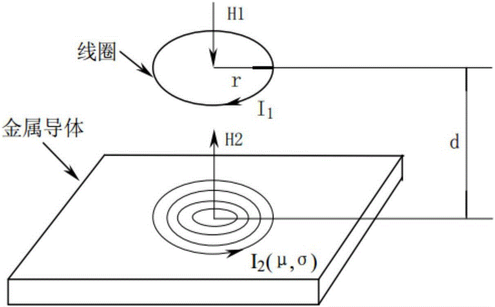
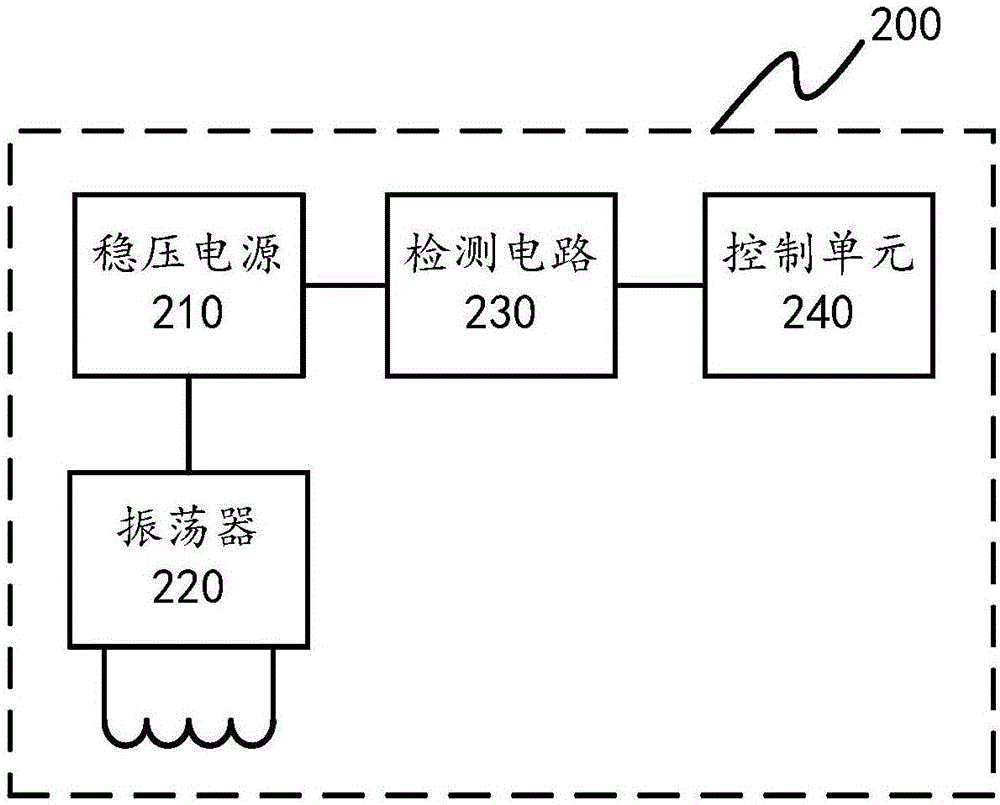
[0019] figure 2 A schematic diagram of a rotational speed sensor 200 according to some embodiments of the present invention is shown. Such as image 3 As shown, the rotational speed sensor 200 includes a regulated power supply 210 , an oscillator 220 , a detection circuit 230 and a control unit 240 . The oscillator 220 has a coil relative to a metal conductor. Here, the regulated power supply 210 is a DC regulated power supply,...


PUM


Abstract

The invention discloses a rotating speed sensor, which comprises a voltage-stabilized power supply, an oscillator and a detection circuit, wherein a power supply input end of the oscillator is coupled to an output end of the voltage-stabilized power supply, and the oscillator is provided with a coil which is arranged opposite to a metal conductor; the oscillator stops oscillating when the distance between the metal conductor and the coil is less than a critical threshold, so that the voltage-stabilized power supply is facilitated to reduce current of an output end in a step manner; and the detection circuit is applicable to detecting an electric signal corresponding to a current value of the output end of the voltage-stabilized power supply. A control unit is coupled to the detection circuit, and is applicable to determining whether the oscillator stops oscillating or not according to the electric signal and recording a pulse at each time when the oscillator is determined to stop oscillating.

Description

technical field [0001] The invention relates to the technical field of equipment monitoring, in particular to a rotational speed sensor. Background technique [0002] A speed sensor is a sensor that converts the speed of a rotating object into electrical output. A common rotational speed sensor is, for example, a Hall type or an eddy current type. When the device under test has a raised (or depressed) magnetic or magnetic material, when the device under test rotates, the sensor outputs a pulse signal related to the rotation frequency to achieve the purpose of speed detection. figure 1 The working principle of the eddy current sensor is shown. The working mechanism of the eddy current speed sensor system is an LC oscillator composed of a probe (that is, a wound coil, which is equivalent to an inductance) and an internal circuit. An alternating magnetic field H1 is generated around the probe head. If there is no metal conductor material approaching within the range of the ...

Claims


Application Information

Patent Timeline
Patent Type & Authority Applications(China)
IPC IPC(8): G01P3/481G08C17/02
CPCG01P3/487G08C17/02
Inventor 许凌波程鑫陈桂梅王祖军王之剑贾维银
Owner ANHUI RONDS SCI & TECH INC CO
Why Eureka
Try Eureka