Non-contact high-precision shaft current measuring device

A measuring device, non-contact technology, applied in the direction of using digital measurement technology for measurement, etc., can solve the problems that the magnetic poly ring and magnetic sensor cannot meet the requirements, and the anti-interference ability is insufficient.

Active Publication Date: 2016-11-09
NO 719 RES INST CHINA SHIPBUILDING IND
View PDF13 Cites 15 Cited by
  • Summary
  • Abstract
  • Description
  • Claims
  • Application Information

AI Technical Summary

Problems solved by technology

However, usually the magnetic gathering ring is designed as a whole ring. Although the measurement accuracy is high, the anti-interference ability is slightly insufficient.
Considering the complex electromagnetic environment around the ship's propulsion shaft or motor rotor shaft, th

Method used


Image

  • Non-contact high-precision shaft current measuring device
  • Non-contact high-precision shaft current measuring device
  • Non-contact high-precision shaft current measuring device

Examples


Embodiment Construction

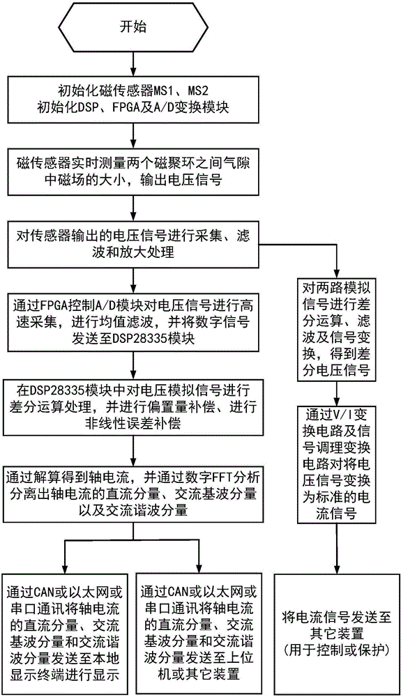
[0040] The technical solution of the present invention will be described in more detail below in conjunction with the accompanying drawings.

[0041] figure 1 A non-contact high-precision shaft current measuring device described in the present invention is provided.

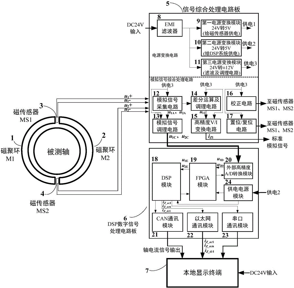
[0042] Such as figure 1 As shown, the non-contact high-precision shaft current measuring device includes a first magnetic gathering ring M1 (1), a second magnetic gathering ring M2 (2), a first magnetic sensor MS1 (3), a second magnetic sensor MS2 (4), integrated signal processing circuit board 5 , DSP digital signal processing circuit board 6 and local display terminal 7 .

[0043] The first magnetic gathering ring M1(1) and the second magnetic gathering ring M2(2) are made of materials with high magnetic permeability, such as iron-based amorphous or iron-based nanocrystals; the first magnetic sensor MS1 (3) and the second magnetic sensor MS2 (4) select a high-precision, high-resolution, high-sensitivity, low...


PUM


Abstract

The invention relates to a non-contact high-precision shaft current measuring device. The non-contact high-precision shaft current measuring device comprises a first magnetic concentrating ring M1, a second magnetic concentrating ring M2, a first magnetic sensor MS1, a second magnetic sensor MS2, a signal comprehensive processing circuit board, a DSP digital signal processing circuit board and a local display terminal. The first magnetic sensor MS1 and the second magnetic sensor MS2 measure magnetic field signals of an air gap between the first magnetic concentrating ring M1 and the second magnetic concentrating ring M2 and output voltage signals representing the magnitude of the magnetic field. After signal modulation by the signal comprehensive processing circuit board and the DSP digital signal processing circuit board, the current signal of a tested shaft is displayed on the local display terminal. The shaft current measuring device is high in interference resistance, high in resolution, high in detection precision, good in linearity and high in response speed; the requirements of tested current sources with various shape sizes are met, the mounting and dismounting are simple, the maintenance is convenient, the device is especially suitable for weak current signal measurement of a ship propulsion shaft, a motor rotor shaft or other large-diameter rotation shafts, and the general applicability is realized.

Description

technical field [0001] The invention relates to the field of signal detection and transformation, in particular to a non-contact high-precision shaft current measuring device. Background technique [0002] Due to anti-corrosion requirements, ships are generally equipped with impressed current cathodic protection systems. The electrical current supplied by this system induces a current in the shaft of the ship. Measuring the size of the shaft current of the ship can effectively understand the anti-corrosion condition of the ship. [0003] Due to the uneven magnetic field in the space where the rotor shaft of the generator is located, a voltage is induced at both ends of the rotor shaft, thereby generating a current signal. The long-term existence of shaft current will cause the bearing temperature to rise and affect the service life of the motor. Measuring the magnitude of the current on the shaft can assist in observing the operation of the motor, provide a timely alarm s...

Claims


Application Information

Patent Timeline
IPC IPC(8): G01R19/25
CPCG01R19/25
Inventor 徐林耿攀余定峰左超杨文铁杨勇张平王建勋孙瑜魏华徐正喜陈涛罗伟李文华郑中详谢炜姜波吴浩伟吴大立蔡凯余跃听雷津袁阳
Owner NO 719 RES INST CHINA SHIPBUILDING IND
Why Eureka
Try Eureka