An optical probe and electromagnetic field measurement equipment and their measurement method

An optical probe and electromagnetic field technology, applied in the direction of electromagnetic field characteristics and the use of optical devices to transmit sensing components, can solve problems such as the selection of probe sensitivity that cannot ensure that the probe works at the best working point, and the low intensity of reflected signal light, etc. Achieve the effect of high integration, strong anti-interference ability and strong reflected signal

Active Publication Date: 2020-07-14
CHINA ELECTRONIC TECH GRP CORP NO 38 RES INST
View PDF12 Cites 0 Cited by
  • Summary
  • Abstract
  • Description
  • Claims
  • Application Information

AI Technical Summary

Problems solved by technology

However, the above two technologies only use electro-optic crystals as sensing probes, need external polarization controllers, optical analyzers and other separate optical devices, and only use the cross-section reflection of electro-optic crystals to obtain reflected signals, so the light intensity of reflected signals is relatively small susceptible to external disturbances
At the same time, this technology does not control the polarization state of the incident laser, and cannot guarantee that the probe works at the best working point and realizes the selection of probe sensitivity according to the needs of the workplace. Therefore, a higher integration and better stability is proposed. , Micro-optical probes with adjustable sensitivity for electromagnetic field measurement are necessary

Method used


Image

  • An optical probe and electromagnetic field measurement equipment and their measurement method
  • An optical probe and electromagnetic field measurement equipment and their measurement method
  • An optical probe and electromagnetic field measurement equipment and their measurement method

Examples


Embodiment Construction

[0017] The present invention will be described in further detail below in conjunction with the examples. It should be understood that the specific embodiments described here are only used to explain the present invention, not to limit the present invention.

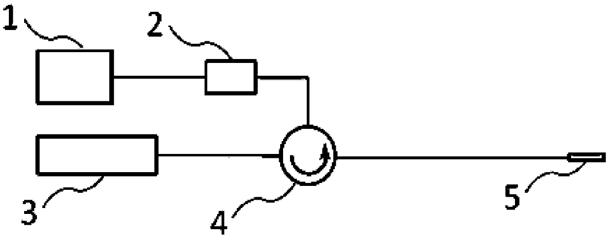
[0018] see figure 1 , figure 1 A schematic diagram of the structure of the electromagnetic field measurement device provided by the preferred embodiment of the present invention, that is, a schematic diagram of the working mode of the micro-optical probe for electromagnetic field measurement with adjustable sensitivity of the electromagnetic field measurement device. The electromagnetic field measurement equipment includes a spectrum analyzer 1 , a photodetector 2 , a laser 3 , an optical circulator 4 , and an optical probe 5 . The optical probe 5 is an optical probe with adjustable sensitivity for electromagnetic field measurement. The laser light emitted by the laser 3 enters the optical probe 5 in the measured elect...


PUM


Abstract

The invention discloses an optical probe, an electromagnetic field measurement device and measurement methods thereof. The optical probe comprises a collimator, a polarizer, a quartz wave plate, an electro-optic crystal, a high-reflectivity dielectric slice, an incident optical fiber and a quartz glass tube, wherein the collimator, the polarizer, the quartz wave plate, the electro-optic crystal and the high-reflectivity dielectric slice are sequentially assembled in the quartz glass tube according to the above sequence; and the incident optical fiber is connected onto the collimator and fixed on the tube wall of the glass tube. The optical probe has the advantages that the size is small; the integration is high; interference to the measured electromagnetic field is little; the anti-interference ability is high; the spatial resolution is high; the dynamic range is large; the response bandwidth is large; the sensitivity can be designed and adjusted according to demands. The invention also discloses an optical probe measurement method, an electromagnetic field measurement device provided with the optical probe, and an electromagnetic field measurement device measurement method.

Description

technical field [0001] The present invention relates to an optical probe, electromagnetic field measuring equipment and their measurement methods in the field of electromagnetic field measurement, in particular to an optical probe with adjustable sensitivity for electromagnetic field measurement, a measurement method of the optical probe, and a measurement method with the optical An electromagnetic field measuring device of a probe, and a measuring method of the electromagnetic field measuring device. Background technique [0002] Electromagnetic field measurement is a key part in various scientific and technological fields. Process control, electric field monitoring of medical equipment, ballistic control, electromagnetic compatibility measurement, microwave integrated circuit test, strong electric field measurement, etc. are all application fields of electromagnetic field sensors. Traditional electromagnetic field measurement systems usually use active metal probes, which ...

Claims


Application Information

Patent Timeline
Patent Type & Authority Patents(China)
IPC IPC(8): G01R29/08G01D5/30
CPCG01D5/30G01R29/08
Inventor 张业斌田晓光王昌雷武帅张思敏盛永鑫
Owner CHINA ELECTRONIC TECH GRP CORP NO 38 RES INST
Why Eureka
Try Eureka