DC bias feature test circuit and test circuit of capacitor

A characteristic test, DC bias technology, applied in the field of electronics, can solve problems such as instrument burnout

Inactive Publication Date: 2016-11-09
FUZHOU UNIV
View PDF7 Cites 5 Cited by
  • Summary
  • Abstract
  • Description
  • Claims
  • Application Information

AI Technical Summary

Problems solved by technology

The commonly used impedance analyzer or LCR meter is a precision instrument. During the test, there must be no potential difference between the two ends of the device under test, otherwise it is easy to burn out the instrument.

Method used


Image

  • DC bias feature test circuit and test circuit of capacitor
  • DC bias feature test circuit and test circuit of capacitor
  • DC bias feature test circuit and test circuit of capacitor

Examples


Embodiment 1

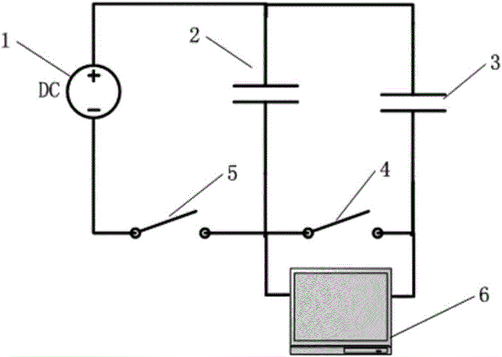
[0049] Embodiment 1: as figure 1 or figure 2 As shown, a DC bias characteristic testing circuit of a capacitor in the present invention includes a DC stabilized power supply 1, a test instrument 6, a first capacitive element 2, a second capacitive element 3, a first switch 5 and a second switch, so The positive pole of the DC stabilized power supply 1 is respectively connected to one end of the first capacitor 2 and one end of the second capacitor 3. The negative pole of the DC stabilized power supply 1 is connected to the other end of the first capacitor 2 through the first switch 5, and the first capacitor The other end of the component 2 is connected to the other end of the second capacitive component 3 through the second switch 4, the two measuring terminals of the test instrument 6 are connected to the two ends of the second switch 4, and the first capacitive component 2 is to be Measuring capacitance; The second capacitive element 3 is the same capacitance to be measur...

Embodiment 2

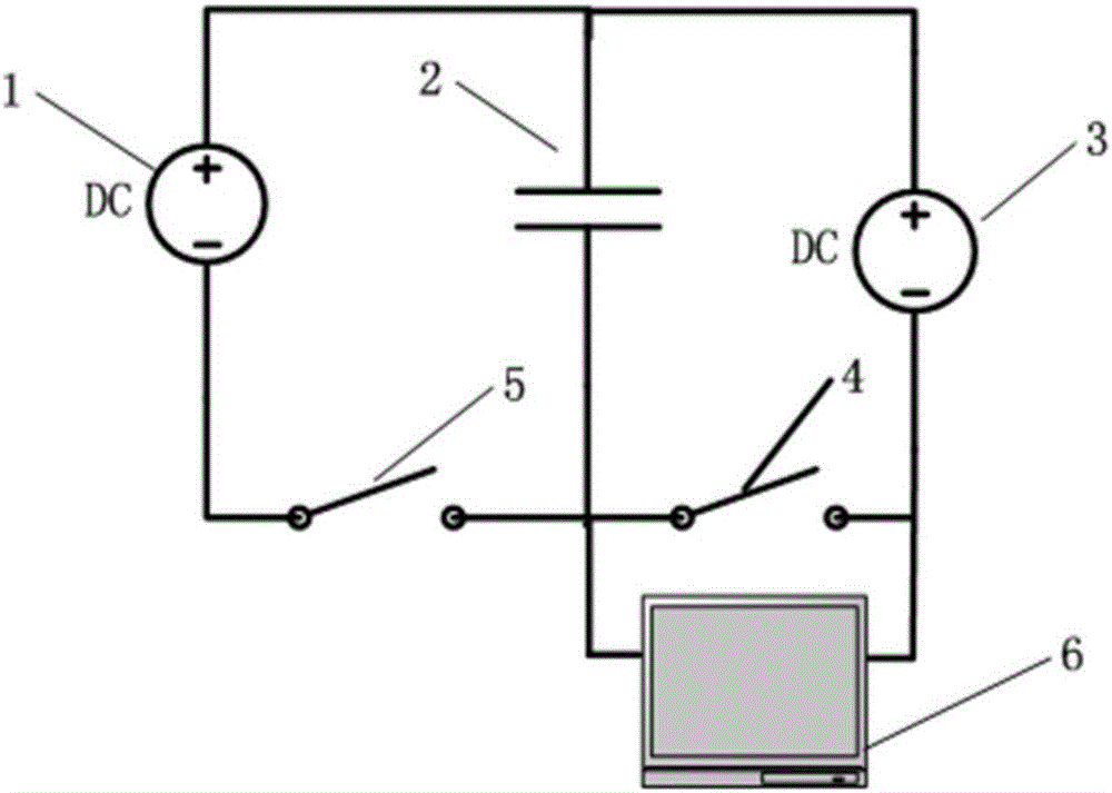
[0069] Such as image 3 As shown, a capacitor DC bias characteristic test circuit of the present invention includes a DC stabilized power supply 1, a test instrument 6, a first capacitive element 2, a second capacitive element 3, a first switch 5 and a second switch 4 The positive pole of the DC stabilized power supply 1 is respectively connected to one end of the first capacitive element 2 and one end of the second capacitive element 3. The negative pole of the DC stabilized voltage power supply 1 is connected to the other end of the first capacitive element 2 through the first switch 5, the second The other end of a capacitive element 2 is connected to the other end of the second capacitive element 3 through the second switch 4, and the two measuring terminals of the test instrument 6 are connected to the two ends of the second switch 4. The first capacitive element 2 is the capacitance to be measured; the second capacitive element 3 is a voltage source with known impedance....

Embodiment 3

[0088] Embodiment 3: as figure 1 As shown, a DC bias characteristic test circuit of a capacitor in the present invention includes a DC stabilized power supply 1, a test instrument 6, a first capacitive element 2, a second capacitive element 3, a first switch 5 and a second switch 4, The positive pole of the DC stabilized power supply 1 is respectively connected to one end of the first capacitive element 2 and one end of the second capacitive element 3. The negative pole of the DC stabilized voltage power supply 1 is connected to the other end of the first capacitive element 2 through the first switch 5. The other end of the capacitive element 2 is connected to the other end of the second capacitive element 3 through the second switch 4, the two measuring terminals of the test instrument 6 are connected to the two ends of the second switch 4, and the first capacitive element 2 is The capacitance to be measured; the second capacitance element 2 is a capacitance with known parame...


PUM


Abstract

The invention discloses a DC bias feature test circuit and test circuit of a capacitor. The circuit comprises a DC voltage-stabilizing power supply, a test instrument, a first capacitor, a second capacitor, a first switch and a second switch, wherein the first capacitor and the second capacitor are connected in parallel, one end of the DC voltage-stabilizing power supply is connected with one end of the first capacitor and one end of the second capacitor, the other end of the DC voltage-stabilizing power supply is connected with the other end of the first capacitor through the first switch, the other end of the first capacitor is connected with the other end of the second capacitor through the second switch, the test instrument is connected with the two ends of the second switch, and the first capacitor is a capacitor to be tested; and the second capacitor is a capacitor to be tested which has the same structure and performance as the first capacitor or a voltage source with known impedance or a capacitor with known parameters. According to the invention, the problem of testing a capacitor load under DC bias is overcome, measured capacitance data of the DC bias in a high-frequency circuit is particularly accurate and effect, and the measured data does not need complex operation.

Description

technical field [0001] The invention relates to the field of electronic technology, in particular to a DC bias characteristic testing circuit and testing method of a capacitor. Background technique [0002] Capacitors often have a certain DC voltage bias in actual operation, and the capacitance characteristics often change under DC voltage bias, including capacitance value, capacitance equivalent series resistance and capacitance equivalent series inductance. At this time, it is not accurate and complete to use the measured capacitance characteristic parameters to characterize the capacitance characteristics under the DC voltage bias when it is static, that is, when there is no DC voltage bias. [0003] The existing technology is mainly aimed at the static characteristics of the capacitor and the characteristic test under the AC load, and fails to realize the accurate measurement of the capacitor characteristic under the DC bias voltage. In the actual circuit, whether it is...

Claims


Application Information

Patent Timeline
Patent Type & Authority Applications(China)
IPC IPC(8): G01R31/00
CPCG01R31/00
Inventor 陈庆彬张伟豪陈为
Owner FUZHOU UNIV
Why Eureka
Try Eureka