

PID parameter adjusting method based on interference compensator
A parameter adjustment and interference compensation technology, applied in the field of PID control, can solve the problems of cumbersome and complicated PID parameter adjustment work, and achieve the effect of saving parameter adjustment time and improving the effect
- Summary
- Abstract
- Description
- Claims
- Application Information
AI Technical Summary
Problems solved by technology
Method used
Image

Examples
Embodiment approach 1
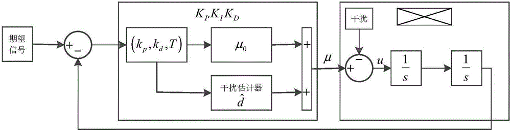
[0052] The first step is to build a closed-loop regulation loop
[0053] Build a tracking error adjustment loop based on PID control. The closed-loop regulation loop of the system includes: control input, controlled object, and control output; the control input includes: reference control signal, PID feedback controller, and the control output indicates the actual state of the controlled object, and the PID feedback controller controls according to the reference control signal The actual state of the controlled object, the disturbed controlled object is a second-order model.
[0054] In the simulation of Matlab\Simulink 2014a, the kinematic model of the quadrotor at the height of the aircraft is divided into: Simplifies to a double differential model: where z and r are heights, and is the quadratic differential in altitude, u and μ are the control input, m is the mass of the aircraft, g is the acceleration of gravity, θ and φ are the pitch angle and roll angle of the a...
Embodiment approach 2
[0070] The first step is to build a closed-loop regulation loop
[0071] Build a tracking error adjustment loop based on PID control. In quadrotor fixed height, the regulation loop of the system includes: control input, controlled object, and control output; the control input includes: remote control control signal, PID feedback controller, the disturbed controlled object is a quadrotor aircraft, and the control The output represents the actual state of the quadrotor height, and the PID feedback controller controls the actual state of the quadrotor according to the control signal of the remote controller.
[0072] The second step is to choose an appropriate positive number k p and k d
[0073] Theoretically, k p and k d It only needs to be a positive number, i.e. k p >0,k d >0, the stability of the closed-loop error system can be guaranteed. In the height control experiment of the quadrotor, in order to make the quadrotor remain stable at a height of 5 meters, the sele...
Embodiment approach 3
[0085] The implementation process of the first step to the fifth step of this embodiment is the same as that of the first step to the fifth step of embodiment 2, and the same parameter k is selected p 、k d and T.
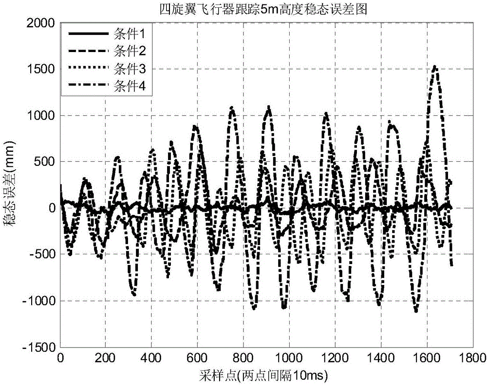
[0086] The difference is that in the fourth step, the height of the quadrotor aircraft is maintained at 5 meters instead of the height maintained at 10 meters. The parameters selected in the height control test of the quadrotor aircraft are shown in Table 3.
[0087] Table 3 Parameters and results of quadrotor aircraft 10-meter height control experiment
[0088]
[0089] The effect of the 10-meter height control experiment of the quadrotor aircraft is as follows: Figure 4 . Although the steady-state peak value of individual signals does not conform to the law, the steady-state error generally increases with the increase of T, and the floating range of the steady-state error will increase accordingly.
[0090] Through Matlab\Simulink 2014a simulation experimen...
PUM
 Abstract
Description
Claims
Application Information