
Drive and control circuit based on IGBT shaping

A driving control circuit, driving circuit technology, applied in the direction of electrical program control, program control in sequence/logic controllers, etc., can solve the problems of low reliability, high circuit cost, poor driving stability, etc., to reduce circuit complexity. and cost, improve stability and reliability, and ensure the effect of reliable shutdown

Active Publication Date: 2016-11-09
SHANGHAI HUTONG ENTERPRISE GROUP
View PDF6 Cites 1 Cited by
  • Summary
  • Abstract
  • Description
  • Claims
  • Application Information

AI Technical Summary

Problems solved by technology

[0005] The invention discloses a drive control circuit based on IGBT shaping, which is used to solve the problems in the prior art that the structure of the isolation drive mode is complex, the circuit cost is high, the drive stability is poor, the reliability is low, and the troubleshooting is difficult

Method used


Image

  • Drive and control circuit based on IGBT shaping
  • Drive and control circuit based on IGBT shaping
  • Drive and control circuit based on IGBT shaping

Examples


Embodiment Construction

[0031] The present invention will be further described below in conjunction with accompanying drawing and embodiment:

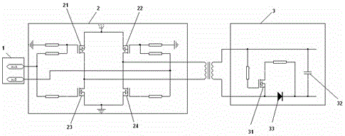
[0032] image 3 It is the circuit diagram of the drive control circuit based on IGBT shaping in the present invention, please refer to image 3 , a drive control circuit based on IGBT shaping, including: a pulse generating circuit 1 connected to a totem pole circuit 2, the totem pole circuit 2 connected to a drive circuit 3, and the totem pole circuit 2 connected to the drive circuit 3 There is a pulse transformer.

[0033] The primary of the pulse transformer of the present invention is connected to the totem pole circuit 2 , and the secondary of the pulse transformer is connected to the drive circuit 3 .

[0034] The pulse generation circuit 1 of the present invention includes two PWM control signal output terminals: a first control signal output terminal and a second control signal output terminal.

[0035] The totem pole circuit 2 of the present invent...


PUM


Abstract

The invention discloses a drive and control circuit based on IGBT shaping. A pulse-generating circuit and a totem pole circuit are connected. The totem pole circuit and a drive circuit are connected. A pulse transformer is connected between the totem pole circuit and the drive circuit. The invention adopts the direct driving mode with the pulse transformer, and thus the complexity and the cost of the circuit are effectively reduced, the driving speed is fast, and no external power supply is required. Self-inductance electric potential of the pulse transformer is utilized to enable a turn-off IGBT grid to be in the backward voltage state, and thus the reliable turn-off of an IGBT is ensured, thereby improving stability and reliability of the circuit.

Description

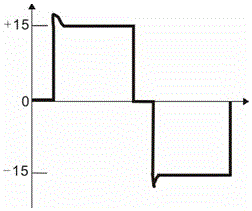
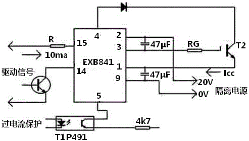
technical field [0001] The invention relates to a control circuit, in particular to a driving control circuit based on IGBT shaping. Background technique [0002] IGBT (Insulated Gate Bipolar Transistor) is a composite fully-controlled voltage-driven power semiconductor device composed of BJT (Bipolar Transistor) and MOS (Insulated Gate Field Effect Transistor). It has the advantages of MOSFET and GTR, high input Impedance, fast switching speed, good thermal stability, on-state voltage drop, high withstand voltage, and large current. [0003] At present, the vast majority of IGBT drives use two methods: direct drive and isolated drive. figure 1 It is the isolated drive chip diagram of the EXB series of Fuji Corporation of Japan. It needs an independent external power supply and the delay of the photoelectric isolation device has limitations on the driving speed. [0004] In the conventional direct drive method, figure 2 Ideally, the gate of the IGBT is turned off by zero...

Claims


Application Information

Patent Timeline
Patent Type & Authority Applications(China)
IPC IPC(8): G05B19/04
CPCG05B19/04
Inventor 郭少朋
Owner SHANGHAI HUTONG ENTERPRISE GROUP
Learn More