Motion state detection device, method and system
A motion state and detection device technology, which is applied in the direction of anti-theft alarm mechanical start, alarms and instruments relying on moving portable items, etc., can solve the problems of single detectable scene and detectable state, large volume, and inability to detect motion state, etc. To achieve the effect of rich sports
- Summary
- Abstract
- Description
- Claims
- Application Information
AI Technical Summary
Problems solved by technology
Method used
Image

Examples
Embodiment 1
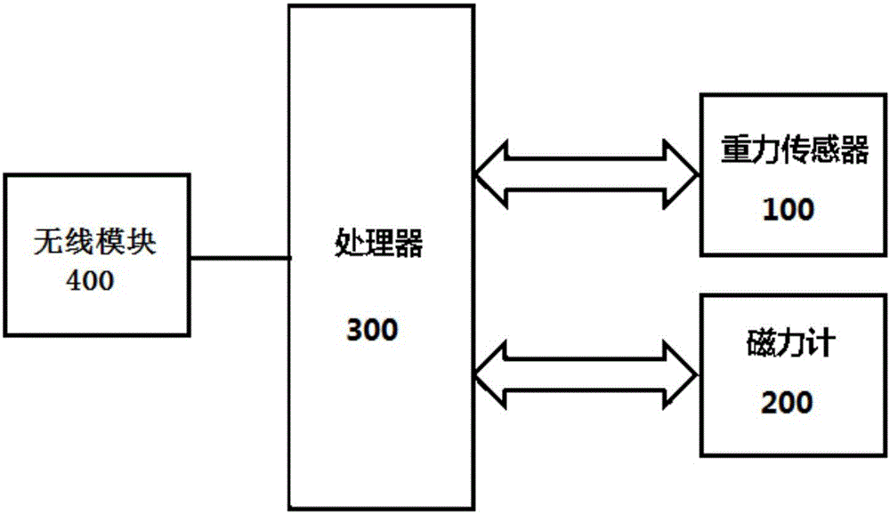
[0022] figure 1 A schematic diagram of a motion state detection device according to an embodiment of the present invention is shown.
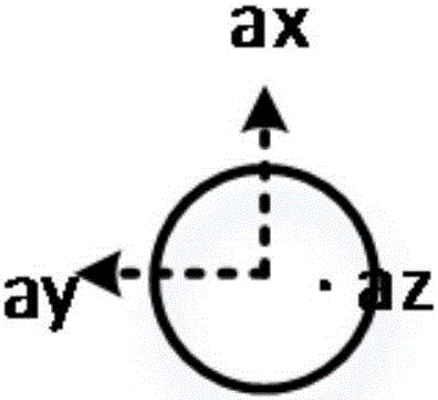
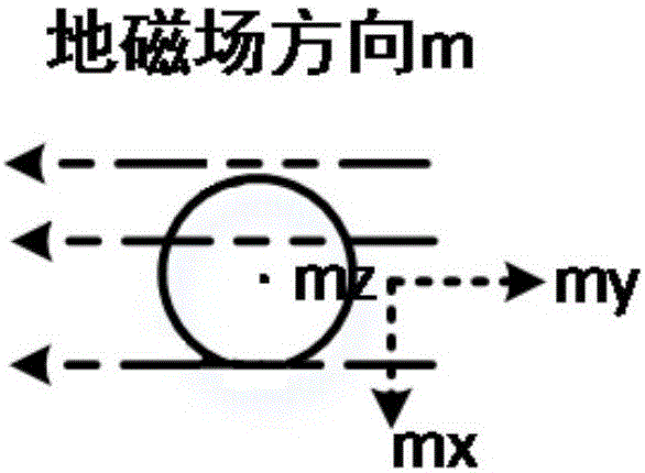
[0023] In this embodiment, the motion state detection device may include: a gravity sensor 100 for sensing acceleration and outputting the X, Y, and Z axis components a of the acceleration x ,a y ,a z ; The magnetometer 200 is used to sense the magnetic field strength and output the X, Y and Z axis components m of the magnetic field strength x ,m y ,m z ; Processor 300, for collecting a x ,a y ,a z and m x ,m y ,m z , for the collected a x ,a y ,a z and m x ,m y ,m z processing to identify the motion state; and the wireless module 400, configured to transmit the identified motion state information. Wherein, the step of identifying the motion state includes: Step 1: Collecting at least one group (a x ,a y ,a z ,m x ,m y ,m z ) for weighted average; Step 2: Obtain another group (a x ,a y ,a z ,m x ,m y ,m z ) and the ...
Embodiment 2
[0048] Figure 5 A flow chart of a motion state detection method according to an embodiment of the present invention is shown.
[0049] In this embodiment, the motion state detection method may include: Step 1: At least one group of (a x ,a y ,a z ,m x ,m y ,m z ) for weighted average; Step 2: Obtain another group (a x ,a y ,a z ,m x ,m y ,m z) and the result of the weighted average; step 3: adapting the difference to the characteristic value of the motion model to judge the motion state of the measured object.
[0050] In this embodiment, the motion state of the measured object is judged by processing the acceleration and magnetic field strength data to adapt to the characteristic value of the motion model, thereby realizing accurate identification of the motion state of the measured object.
[0051] In one example, the step of identifying the motion state may further include: if the adaptation between the difference value and the characteristic value of the motio...
Embodiment 3
[0058] Figure 6 A schematic structural diagram of a motion state detection system according to an embodiment of the present invention is shown.
[0059] In this embodiment, the motion state detection system may include: the motion state detection device according to the present invention; the upper casing 8 and the lower casing 2, and the upper casing 8 and the lower casing 2 form a sealed space to accommodate the motion a state detection device; and an antenna 7 built in the sealed space. Among them, the system can be fixed on the measured object.
[0060] In this embodiment, the motion state detecting device and the antenna according to the present invention are accommodated in the sealed space formed by the upper case and the lower case, so that the whole system is compact and easy to install.
[0061] The system can be pasted on the object to be measured by adhesive 1, and there is no specific restriction on the installation position, such as Figure 7 shown.
[0062]...
PUM
 Abstract
Description
Claims
Application Information
 - R&D
- Intellectual Property
- Life Sciences
- Materials
- Tech Scout
- Unparalleled Data Quality
- Higher Quality Content
- 60% Fewer Hallucinations
Browse by: Latest US Patents, China's latest patents, Technical Efficacy Thesaurus, Application Domain, Technology Topic, Popular Technical Reports.
© 2025 PatSnap. All rights reserved.Legal|Privacy policy|Modern Slavery Act Transparency Statement|Sitemap|About US| Contact US: help@patsnap.com