
Right-angle electrical connector

An electrical connector and connector technology, applied in the direction of connection, fixed connection, and components of the connection device, can solve the problems of poor welding, inconsistent welding, incomplete welding, etc., and achieve good welding results.

Active Publication Date: 2016-11-09
HIROSE ELECTRIC GROUP
View PDF7 Cites 7 Cited by
  • Summary
  • Abstract
  • Description
  • Claims
  • Application Information

AI Technical Summary

Problems solved by technology

The magnitude of this stress and its deviation may cause problems such as inconsistent soldering, incomplete soldering, and poor soldering when the connecting portion is soldered to the corresponding circuit portion of the circuit board by automatic mounting.

Method used


Image

  • Right-angle electrical connector
  • Right-angle electrical connector
  • Right-angle electrical connector

Examples


Embodiment Construction

[0034] Hereinafter, embodiments of the present invention will be described based on the drawings.

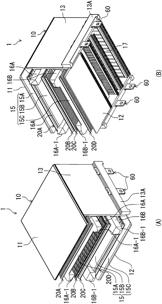
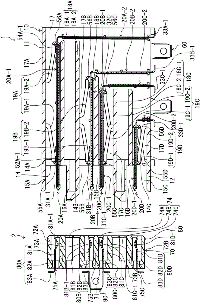
[0035] figure 1 The electrical connectors of this embodiment shown in (A) and (B) are formed in a direction in which a mating connector is fitted and a connection portion soldered to a circuit board (not shown) is arranged in the direction of the circuit board. A so-called right-angle electrical connector (hereinafter referred to as "connector") in which the direction in which the legs of the terminals of the connecting portion extend is at right angles. figure 1 (A) is a perspective view showing the appearance of the connector 1 according to the present embodiment viewed obliquely from above, figure 1 (B) is a perspective view showing the appearance of the connector 1 viewed obliquely from below. figure 2 It is a cross-sectional view of the connector 1 on a plane perpendicular to the width direction of the connector, and shows a cross section of the position of the termin...


PUM


Abstract

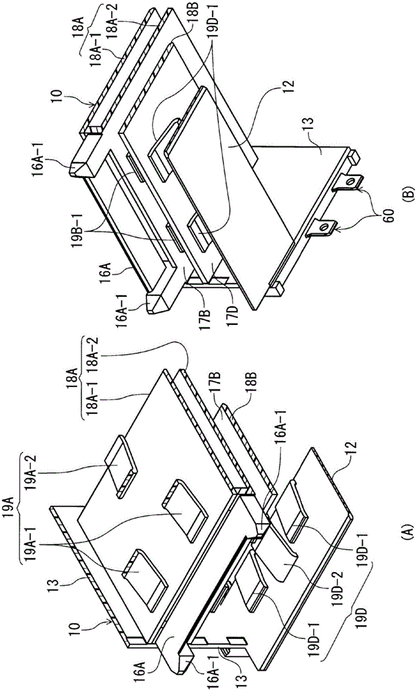
The invention discloses a right-angle electrical connector with which the problem is not encountered even when the positions of the connection components of different types of terminals are not aligned in the vertical direction with respect to the circtui board prior to mounting. In a housing (10) are formed holding grooves (17A to 17D) that permit arm-use blades (20A-1 to 20D-1) of various types of blades (20A to 20D) to be inserted from the rear, connection components (33A-1 to 33D-1) provided to the lower ends of legs (33A to 33D) of conductive bar members (30A to 30D) of the various types of blades (20A to 20D) are located outside the housing (10), the arm-use blades (20A-1 to 20D-1) of the various types of blades (20A to 20D) are able to move in the vertical direction over a specific range within the corresponding holding grooves (17A to 17D), and the various types of blades (20A to 20D) are able to move within a holding space 17.

Description

technical field [0001] The present invention relates to right angle electrical connectors. Background technique [0002] Patent Document 1 discloses a so-called right-angle electrical connector in which a mating direction of a mating connector is at right angles to a direction in which a terminal extends with respect to a circuit board. In the terminal of this patent document 1, the direction in which the fitting portion having the contact portion that contacts the terminal of the mating connector extends and the direction in which the leg portion extending at the lower end having the connecting portion soldered to the circuit board are at right angles to each other. , the fitting portion and the leg portion are connected by an L-shaped bending portion, and form a right-angled shape as a whole. The terminals having this rectangular shape are produced as two types of terminals with different overall lengths. The bent portion of the shorter terminal is located inside the bent...

Claims


Application Information

Patent Timeline
IPC IPC(8): H01R12/57H01R12/72H01R13/02H01R13/46H01R13/516
CPCH01R12/57H01R12/724H01R13/02H01R13/46H01R13/516H01R12/707H01R12/737
Inventor 永田雅一松泽敦史
Owner HIROSE ELECTRIC GROUP
Learn More