Power distribution cabinet

A technology for power distribution cabinets and cabinets, applied in substation/power distribution device shells, electrical components, substation/switch layout details, etc.

Active Publication Date: 2016-11-09
ZTT ELECTRICAL TECH CO LTD
View PDF8 Cites 20 Cited by
  • Summary
  • Abstract
  • Description
  • Claims
  • Application Information

AI Technical Summary

Problems solved by technology

However, when the external environment is high temperature and high humidity, it is not

Method used


Image

  • Power distribution cabinet
  • Power distribution cabinet
  • Power distribution cabinet

Examples


Embodiment 1

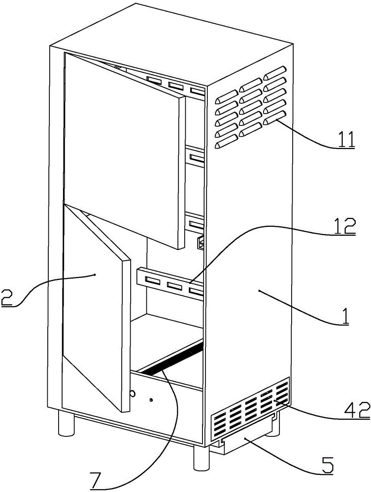
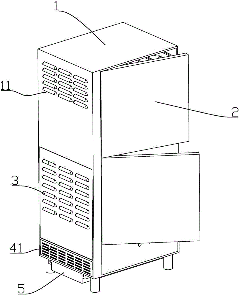
[0067] according to Figure 1 to Figure 14 As shown, the present embodiment is a power distribution cabinet, which includes a cabinet body 1 with an open front end, and a cabinet door 2 connected to the front end of the cabinet body through a hinge;

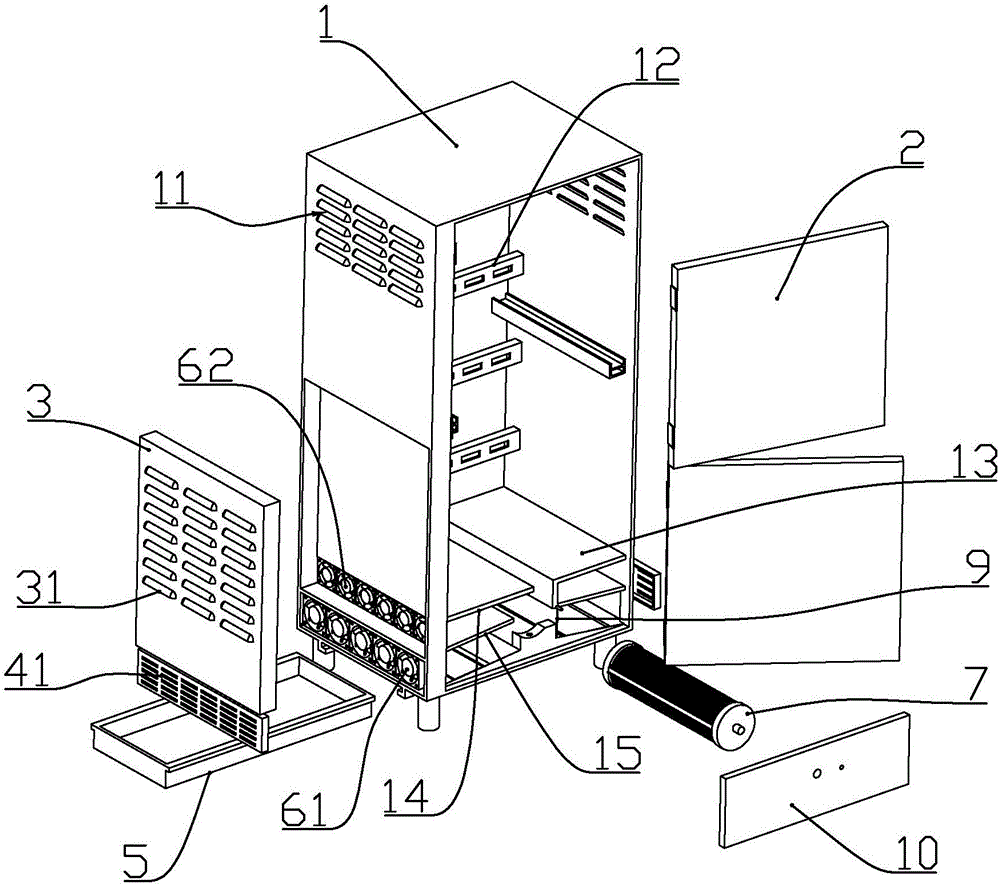
[0068] The bottom of the cabinet body is formed with a high middle and low slope plate 16 on both sides; the rear cabinet plate is located on the rear side of the cabinet body in the cabinet body, and a stepping motor is installed on the bottom of the rear cabinet plate located above the middle position of the slope plate 8. The output shaft of the stepping motor is connected with a cooling plate assembly 7 arranged horizontally along the front and back direction of the cabinet.

[0069] The cooling chip assembly 7 includes two circular end blocks 74 of plastic material, more than one semiconductor cooling chip 71 connected between the two end blocks, a condensation aluminum seat 72 connected to one side of the semiconductor cool...

Embodiment 2

[0083] according to Figure 1 to Figure 14 As shown, the present embodiment is a power distribution cabinet, which includes a cabinet body 1 with an open front end, and a cabinet door 2 connected to the front end of the cabinet body through a hinge;

[0084] The bottom of the cabinet body is formed with a high middle and low slope plate 16 on both sides; the rear cabinet plate is located on the rear side of the cabinet body in the cabinet body, and a stepping motor is installed on the bottom of the rear cabinet plate located above the middle position of the slope plate 8. The output shaft of the stepping motor is connected with a cooling plate assembly 7 arranged horizontally along the front and back direction of the cabinet.

[0085] The cooling chip assembly 7 includes two circular end blocks 74 of plastic material, more than one semiconductor cooling chip 71 connected between the two end blocks, a condensation aluminum seat 72 connected to one side of the semiconductor cool...


PUM

PropertyMeasurementUnit
Central angleaaaaaaaaaa
Apertureaaaaaaaaaa
Widthaaaaaaaaaa

Abstract

The invention discloses a power distribution cabinet. The power distribution cabinet comprises a cabinet body whose front end is opened and a cabinet door connected to the front end of the cabinet body through a hinge. A bottom in the cabinet body forms a slope plate whose a middle portion is high and two sides are low. A stepping motor is installed above a lower portion of a rear cabinet plate located on a rear side of the cabinet body in the cabinet body, wherein the lower portion of the rear cabinet plate is located at a middle position of the slope plate. An output shaft of the stepping motor is connected to a refrigeration sheet assembly which is horizontally arranged along a forward and backward direction of the cabinet body. A lower portion of a front side of the cabinet body is installed with a front baffle plate. A first diversion board is fixedly connected to a left and upper portion of the refrigeration sheet assembly in the cabinet body. A baffle plate is fixedly connected to a right side of the refrigeration sheet assembly in the cabinet body. An upper air inlet is formed between the first diversion board and a second diversion board of a left side of the cabinet body. An upper fan is installed in the upper air inlet. An upper air inlet plate is connected above the upper air inlet of an outer side of the cabinet body. Left and right sides of an upper portion of the cabinet body form air outlets. The structure is simple and compact and the power distribution cabinet is suitable for being used under various kinds of complex condition environments.

Description

technical field [0001] The invention belongs to the field of electric equipment, and in particular relates to a structure of a power distribution cabinet. Background technique [0002] The power distribution cabinet is to assemble switchgear, measuring instruments, etc. in a closed or semi-closed metal cabinet according to the requirements of electrical wiring. The Chinese patent with the document number CN104613672A discloses a semiconductor high-voltage cabinet dehumidification device. The shape of the invention is a sheet-like body made of semiconductor refrigeration sheets, and its heating surface is attached to the high-voltage power distribution cabinet through heat-conducting silicone grease. On the inner wall of the metal shell, its cooling surface is close to a layer of metal film. The outer surface of the metal film is a polished plane. There is an inclined bus bar on the plane. The bus bar leads to the high-voltage power distribution through the return pipe. outs...

Claims


Application Information

Patent Timeline
IPC IPC(8): H02B1/56H02B1/30
CPCH02B1/30H02B1/565
Inventor 周佳斌
Owner ZTT ELECTRICAL TECH CO LTD
Why Eureka
Try Eureka