Automotive rotating motor

A technology for rotating electrical machines and vehicles, applied to the shape/style/structure of the winding insulation, the shape/style/structure of the winding conductor, etc., can solve the problems of cost increase, achieve the effect of improving the cooling effect and improving the maximum performance

Inactive Publication Date: 2016-11-09
MITSUBISHI ELECTRIC CORP
View PDF5 Cites 3 Cited by
  • Summary
  • Abstract
  • Description
  • Claims
  • Application Information

AI Technical Summary

Problems solved by technology

[0010] The cooling method of Patent Document 1 has the problem of requiring additional components such as pumps for spraying cooling oil, resulting in an increase in cost

Method used


Image

  • Automotive rotating motor
  • Automotive rotating motor
  • Automotive rotating motor

Examples


Embodiment approach 1

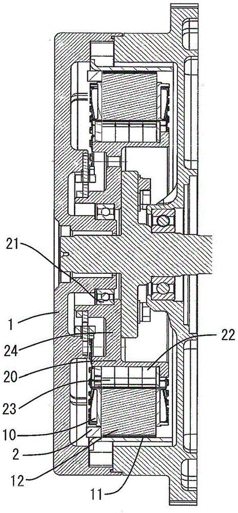
[0025] figure 1 It is a sectional view showing the structure of the rotating electrical machine in Embodiment 1 of the present invention. Such as figure 1 As shown, the rotating electric machine in Embodiment 1 includes a stator 10 and a rotor 20 . A rotor core 22 made of laminated steel plates is arranged on the outer peripheral side of the rotor 20 , and a permanent magnet 23 is arranged inside it. The rotor core 22 is fixed such that its inner peripheral portion is press-fitted into the outer peripheral portion of a rotor boss portion 24 .

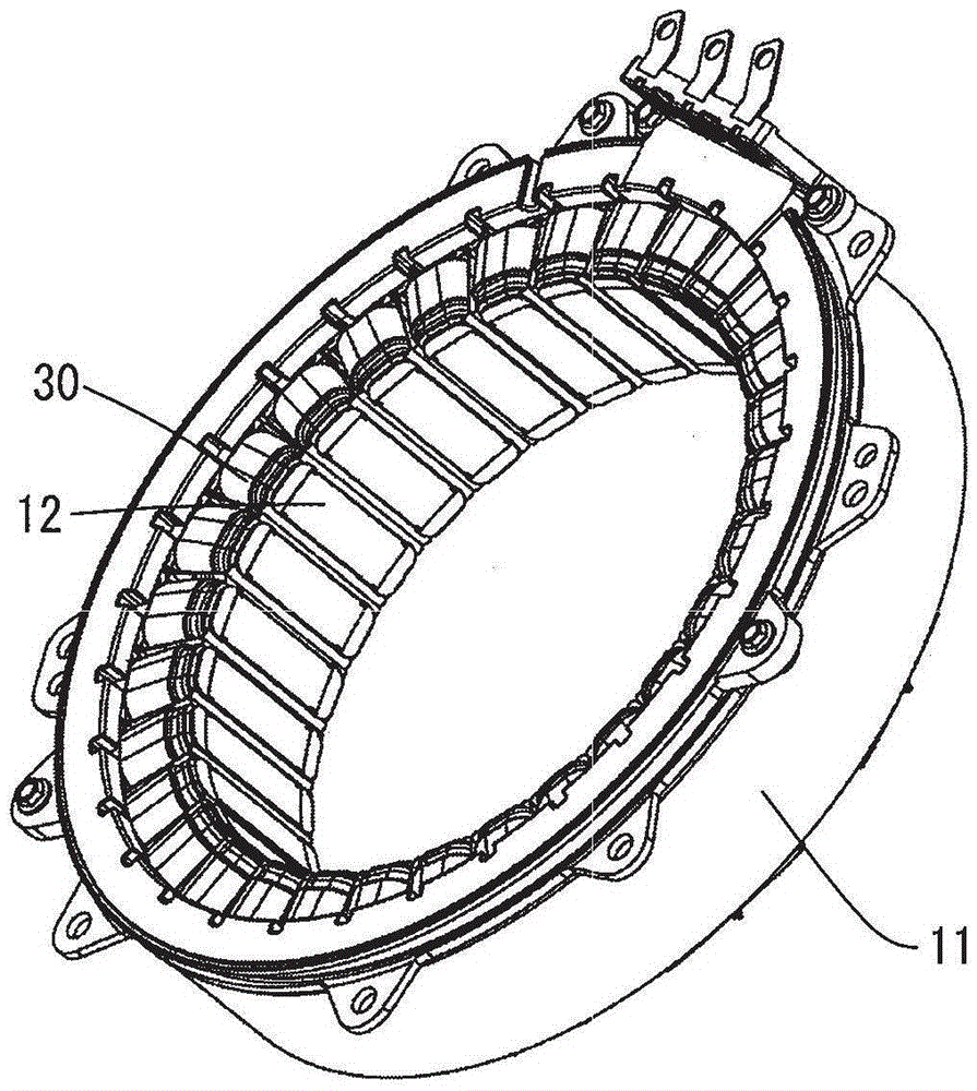
[0026] On the other hand, the stator 10 is configured by press-fitting an iron core 12 made of the same laminated steel plates into the inner periphery of an annular frame 11 . A predetermined gap is provided between the inner circumference of the core 12 and the outer circumference of the opposing rotor core 22 .

[0027] The rotor 20 is held rotatably relative to the housing 1 by a bearing 21 disposed on the inner periphery of the...

Embodiment approach 2

[0037] In this Embodiment 2, the method of improving the cooling effect by improving the arrangement|positioning of the last turn part 32 of a coil is demonstrated.

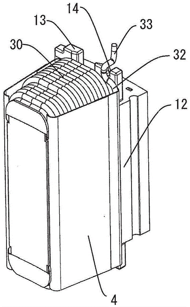
[0038] Figure 5 It is a perspective view showing a detailed configuration of a winding portion of a stator of a rotating electrical machine according to Embodiment 2 of the present invention. Figure 5 In , the state without the outermost insulating paper 4 is shown. Image 6 It is a cross-sectional view of a winding portion of a stator of a rotating electrical machine according to Embodiment 2 of the present invention.

[0039] In Embodiment 2, in the step of forming the final turn portion 32 of the coil, as Figure 5 As shown, the linear portion 34 is arranged so that it moves toward the center portion of the groove. Thus, if Image 6 As shown, the corner portion on the outer peripheral side of the insulating paper 4 is made to protrude toward the opposite coil side from the extension line of the core divi...


PUM


Abstract

The invention provides an automotive rotating motor, wherein coil cooling effect and maximal performance are improved according to a method of no component increase. The automotive rotating motor comprises the components of a rotor; a stator which is configured oppositely to the outer circumferential surface of the rotor and is provided with an iron core (12) that are divided into a plurality of segments; a coil which is coiled on insulators mounted on the upper surface and the lower surface of the iron core that is divided into a plurality of segments and is provided with a coil end that projects to the axial end surface; and insulating paper (4) which is configured between the side surfaces of adjacent coils in each trough of the iron core that is divided into the plurality of segments, wherein in the coil and in the trough, an outmost layer part (31), namely the side surface is configured in a stepped manner, and furthermore a plurality of gaps (3) are formed between the outmost layer part and the insulating paper.

Description

technical field [0001] The present invention relates to a rotating electric machine for a vehicle capable of improving the maximum performance of the electric rotating machine, and more particularly to a stator winding structure of the electric rotating machine. Background technique [0002] In a hybrid vehicle equipped with an engine and a rotary electric machine, a thin and flat brushless electric motor sandwiched between the engine and the transmission is often used. When adopting such a brushless motor, it is preferable to use a rotating electrical machine with a large diameter and a short shaft length in consideration of mountability on existing vehicles. Therefore, in many cases, a concentrated winding type rotating electrical machine capable of shortening the height of the coil ends is used. [0003] In the case of adopting a concentrated winding type rotating electrical machine, the length of the entire coil is shortened, the coil resistance is reduced, and heat gen...

Claims


Application Information

Patent Timeline
Patent Type & Authority Applications(China)
IPC IPC(8): H02K3/28H02K3/34H02K3/24
CPCH02K3/34H02K3/28H02K3/24
Inventor 西川健尾岛宏一
Owner MITSUBISHI ELECTRIC CORP
Why Eureka
Try Eureka