Automatic dust removal heat dissipation monitoring camera

A monitoring camera and self-dust removal technology, applied in the field of cameras, can solve problems such as easy damage, impact on shooting quality, and unfavorable heat dissipation of equipment, and achieve the effects of improving work effect, reducing work pressure and prolonging service life.

Inactive Publication Date: 2016-11-09
苏州亿泰信息科技有限公司
View PDF5 Cites 32 Cited by
  • Summary
  • Abstract
  • Description
  • Claims
  • Application Information

AI Technical Summary

Problems solved by technology

[0002] Security monitoring system is a new major that people pay more and more attention to. As far as the current development is concerned, the application of security system engineering is becoming more and more popular, and the technological content is getting higher and higher; especially the advent of the information age provides an opportunity for the development of this major. The traditional monitoring system includes front-end cameras, transmission cables, and video monitoring platforms. Cameras can be divided into network digital cameras and analog cameras, which can be used as front-end video image signal collection. Video monitoring is intuitive, accurate, timely, and rich in information. It is widely used in many occasions; in recent years, with the rapid development of computer, network, image processing and transmission technology, video surveillance technology has also made great progress. Existing surveillance cameras are gener

Method used


Image

  • Automatic dust removal heat dissipation monitoring camera
  • Automatic dust removal heat dissipation monitoring camera

Examples


Embodiment

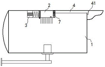
[0018] exist figure 1 , figure 2 In the illustrated embodiment, the self-dust-removing and heat-dissipating monitoring camera includes a housing 1 and a lens,

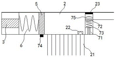
[0019] A heat-absorbing chamber 2 is fixed inside the housing 1, an electromagnet element 3 is installed at the bottom of the heat-absorbing chamber 2, and an air injection port is opened on the top; an air guide pipe 4 is connected to the air ejection port, and the air outlet end of the air guide pipe 4 41 extends out of the housing 1 and is close to the lens; the air outlet direction of the air outlet 41 of the air guide tube 4 is parallel to the mirror surface; heat absorbing fins 21 are installed on the outer wall of the heat absorbing chamber 2;

[0020] A piston plate 5 made of ferromagnetic material is slidably installed in the heat-absorbing cavity 2, and the piston plate 5 is connected with the electromagnet element 3 through a compression spring 6; Air intake pipe 22, the one-way air intake pipe 22 is clos...


PUM


Abstract

The invention relates to an automatic dust removal heat dissipation monitoring camera. The automatic dust removal heat dissipation monitoring camera comprises a shell and a lens. A heat absorption cavity is fixed in the shell. An electromagnet element is mounted at the bottom of the heat absorption cavity. An air jet hole is arranged at the top of the heat absorption cavity. An air guide tube communicates with the air jet hole. The air outlet end of the air guide tube stretches out of the shell and is close to the lens. A piston plate made of a ferromagnetic material is mounted in the heat absorption cavity in a sliding mode. The piston plate and the electromagnet element are connected through a pressure spring. A unidirectional air inlet tube is mounted on a side wall of the heat absorption cavity. The unidirectional air inlet tube is close to the top of the heat absorption cavity. A normally closed pressure valve is mounted at the air jet hole. The normally closed pressure valve is close to a pressure sensitive switch. The pressure sensitive switch is connected with the circuit of the electromagnet element in series. The monitoring camera is simple in structure and convenient to maintain, and the service life is effectively prolonged.

Description

technical field [0001] The invention relates to a security equipment, in particular, a camera. Background technique [0002] Security monitoring system is a new major that people pay more and more attention to. As far as the current development is concerned, the application of security system engineering is becoming more and more popular, and the technological content is getting higher and higher; especially the advent of the information age provides an opportunity for the development of this major. The traditional monitoring system includes front-end cameras, transmission cables, and video monitoring platforms. Cameras can be divided into network digital cameras and analog cameras, which can be used as front-end video image signal collection. Video monitoring is intuitive, accurate, timely, and rich in information. It is widely used in many occasions; in recent years, with the rapid development of computer, network, image processing and transmission technology, video surv...

Claims


Application Information

Patent Timeline
IPC IPC(8): H04N5/225G03B17/55
CPCG03B17/55H04N23/51H04N23/55
Inventor 胡振强
Owner 苏州亿泰信息科技有限公司
Why Eureka
Try Eureka