AI technical title is built by Patsnap AI team. It summarizes the technical point description of the patent document.
A manufacturing method and metal technology, applied in the direction of metal layered products, manufacturing tools, metal processing equipment, etc., can solve the problems of reduced production efficiency
Inactive Publication Date: 2016-11-09
TOYO KOHAN CO LTD
View PDF10 Cites 12 Cited by
Summary
Abstract
Description
Claims
Application Information
AI Technical Summary
This helps you quickly interpret patents by identifying the three key elements:
Problems solved by technology
Method used
Benefits of technology
Problems solved by technology
[0003] However, in the above-mentioned manufacturing method (Patent Document 1), in order to obtain a sufficient bonding force of the metal laminate, the oxide film on the surface layer of the bonded surface must be completely removed, and it takes time to perform sputter etching to completely remove the oxide film.
Therefore, especially in the case of continuous production of metal laminated materials, there is a problem of lowering production efficiency, and there is room for further improvement.
Method used
Image
Click on the blue label to locate the original text in one second.
Reading with bidirectional positioning of images and text.
Examples
Embodiment 1
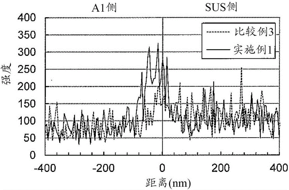
[0051] SUS304-BA (thickness 0.05mm) was used for stainless steel, and A1050-H18 (thickness 0.18mm) was used for aluminum. The surface of SUS304-BA and A1050-H18 was measured using a scanning Auger electron spectroscopy (AES). 150nm.
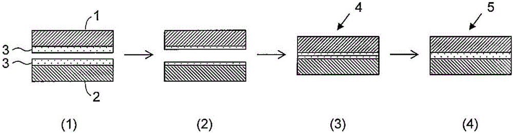
[0052] Next, sputtering treatment was performed on SUS304-BA and A1050-H18. The sputtering treatment of SUS304-BA is carried out in a vacuum of 0.1Pa with a plasma power of 800W and a linear velocity of 3.5m / min; the sputtering treatment of A1050-H18 is carried out in a vacuum of 0.1Pa with a plasma power of 2600W and a linear velocity of 3.5m / min, the surface adsorption layer of SUS304-BA and A1050-H18 is completely removed. Ar was used as an inert gas. The etching amount of SUS304-BA is about 2nm, and the etching amount of A1050-H18 is about 6nm. At room temperature, the sputtered SUS304-BA and A1050-H18 were temporarily bonded by seam welding with a rolling line load of 2tf / cm (rolling load 0.4MN) to form a laminated material.
[0053] AE...
Embodiment 2~5 and comparative example 5~7
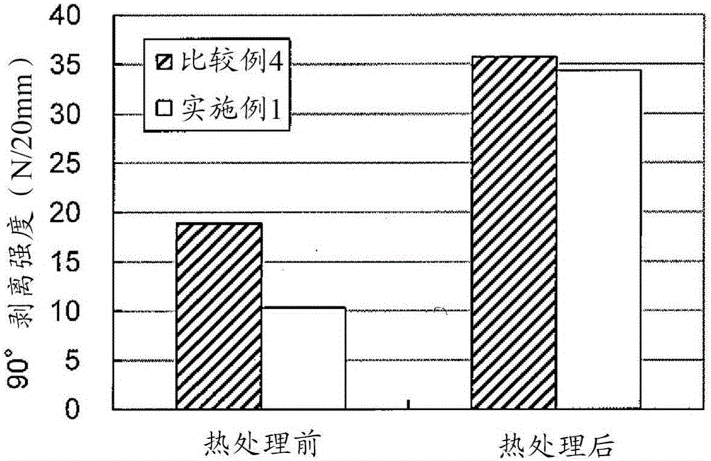
[0068] In Examples 2 to 5 and Comparative Examples 5 to 7, the influence of the temperature of the heat treatment of the temporarily bonded laminated material on the peel strength and hardness of the obtained metal laminated material was investigated.
[0069] In Examples 2 to 5 and Comparative Examples 5 to 7, SUS304-1 / 2H with a thickness of 0.1 mm was used instead of SUS304-BA with a thickness of 0.05 mm, and AL1050 (H24) with a thickness of 0.4 mm was used instead of A1050-H18 with a thickness of 0.18 mm , change the line speed from 3.5m / min to 3.0m / min for sputtering treatment, change the rolling line load from 2tf / cm to 2.8tf / cm in seam welding, and implement temporary seam welding Bonding, except that, was the same as in Example 1, and a temporarily bonded laminated material was obtained. The etching amount of SUS304-1 / 2H is 3nm, and the etching amount of AL1050(H24) is 5nm. The obtained temporarily bonded laminate was heat-treated at a prescribed temperature for 240 mi...
PUM
Property
Measurement
Unit
melting point
aaaaa
aaaaa
thickness
aaaaa
aaaaa
thickness
aaaaa
aaaaa
Abstract
The purpose of the present invention is to provide a method for producing a metal laminate material with higher production efficiency while maintaining sufficient bonding strength. Disclosed is a method for producing a metal laminate material by bonding two plates respectively made of materials M1 and M2, wherein: each of M1 and M2 is a metal or an alloy including at least one type of element selected from the group consisting of Mg, Al, Ti, Cr, Mn, Fe, Co, Ni, Cu, Zn, Nb, Mo, Pd, Ag, In, Sn, Hf, Ta, W, Pb, and Bi; the method comprises a step for subjecting the surfaces to be bonded of the two plates to a sputtering treatment by inert gas ions in a vacuum such that an oxide film on the surface layer remains, a step for temporarily bonding the two plates by roll bonding, and a step for bonding the two plates by heating; and, if the melting point of M1 is Tm1 (K), the melting point of M2 is Tm2 (K), and Tm1>Tm2, the temperature of the heat treatment is higher than or equal to 0.45Tm2 and lower than 0.45Tm1 (and does not exceed Tm2).
Description
technical field [0001] The present invention relates to a method of manufacturing a metal laminate. Background technique [0002] A metal laminate (clad material) is a material formed by bonding two or more different metals together, and is a highly functional metal material that has composite properties that cannot be obtained with a single material. Currently, such metal laminates are produced through various processes such as cleaning of the bonding surface and roll bonding. For example, (Patent Document 1) discloses a method of manufacturing a clad metal plate, that is, in a vacuum chamber, by sputter etching treatment in advance in an extremely low-pressure inert gas atmosphere, the bonding surface of different kinds of metal plates is activated. After chemical treatment, the dissimilar metal sheets are aggregated and combined by cold rolling. According to this method, it is possible to obtain a thin clad metal plate that does not form an alloy layer on the bonding su...
Claims
Application Information
Patent Timeline
Application Date:The date an application was filed.
Publication Date:The date a patent or application was officially published.
First Publication Date:The earliest publication date of a patent with the same application number.
Issue Date:Publication date of the patent grant document.
PCT Entry Date:The Entry date of PCT National Phase.
Estimated Expiry Date:The statutory expiry date of a patent right according to the Patent Law, and it is the longest term of protection that the patent right can achieve without the termination of the patent right due to other reasons(Term extension factor has been taken into account ).
Invalid Date:Actual expiry date is based on effective date or publication date of legal transaction data of invalid patent.

