Refrigeration cycle device
A refrigeration cycle and refrigerant technology, applied in the direction of refrigerators, refrigeration components, refrigeration and liquefaction, etc., can solve the problems of many technical issues, high cost, low performance, etc., and achieve the effect of inhibiting disproportionation reaction
- Summary
- Abstract
- Description
- Claims
- Application Information
AI Technical Summary
Problems solved by technology
Method used
Image
Examples
Embodiment approach 1
[0028] First, the configuration of the refrigeration cycle apparatus will be described.
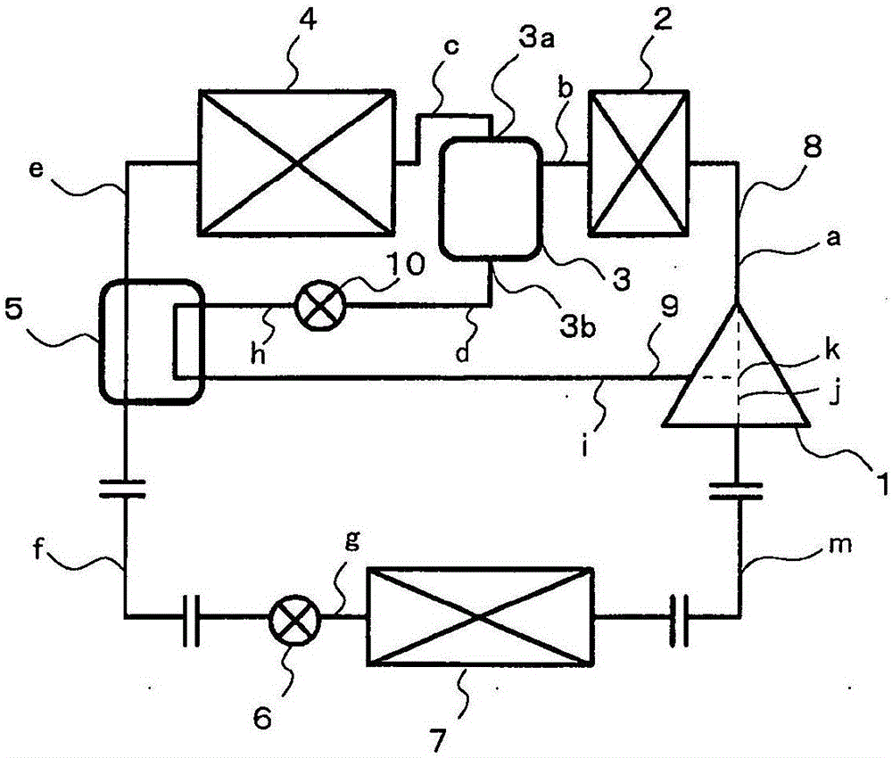
[0029] figure 1 It is a schematic structural diagram of the refrigeration cycle apparatus concerning Embodiment 1.
[0030] Such as figure 1 As shown, the refrigeration cycle device according to the first embodiment uses the refrigerant piping as the main path 8 to sequentially connect the compressor 1 , the first condenser 2 , the gas-liquid separator 3 , the second condenser 4 , and heat exchange between the refrigerants. The device 5, the first expansion valve 6 and the evaporator 7 form a refrigeration cycle. The gas-side outlet 3 a provided on the upper portion of the gas-liquid separator 3 is connected to the second condenser 4 .
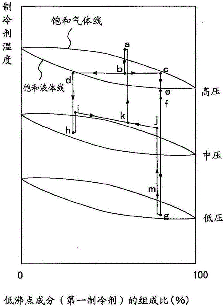
[0031] A liquid-side outlet 3 b provided at a lower portion of the gas-liquid separator 3 is connected to the compressor 1 through a bypass path 9 . The bypass path 9 is connected to an intermediate pressure portion (intermediate pressure=intermediate...
Embodiment approach 2
[0063] First, the configuration of the refrigeration cycle apparatus will be described.
[0064] Since the working refrigerant of the refrigeration cycle apparatus according to the second embodiment is the same as that of the first embodiment, the structural differences will be described.
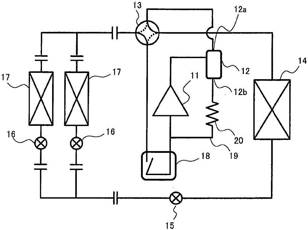
[0065] image 3 It is a schematic structural diagram of the refrigeration cycle apparatus concerning Embodiment 2.
[0066] Such as image 3 As shown, the refrigeration cycle device involved in Embodiment 2 is sequentially connected with a compressor 11, an oil separator 12, a four-way valve 13, an outdoor heat exchanger 14, an outdoor expansion valve 15, an indoor expansion valve 16, an indoor heat exchanger 17, The four-way valve 13 and the accumulator 18 form a refrigeration cycle. A plurality of indoor expansion valves 16 and indoor heat exchangers 17 are connected in parallel, and the gas-side outlet 12 a of the oil separator 12 is connected to the four-way valve 13 . Furthermore, ...
Embodiment approach 3
[0094] First, the configuration of the refrigeration cycle apparatus will be described.
[0095] Since the working refrigerant of the refrigeration cycle apparatus according to the third embodiment is the same as that of the first embodiment, the structural differences will be described.
[0096] Figure 4 It is a schematic structural diagram of the refrigeration cycle apparatus concerning Embodiment 3.
[0097] Such as Figure 4 As shown, the cold cycle device related to Embodiment 3 uses refrigerant piping to sequentially connect the compressor 30, the four-way valve 31, the use-side heat exchanger 32, the subcooler 33, the expansion valve 34 as the first decompression device, and the The heat source side heat exchanger 35 is configured and accommodated in the refrigeration cycle unit 100 .
[0098] And, the composition separation circuit is composed of a refrigerant rectifier 40 as a composition separation mechanism, a refrigerant storage 41 for storing refrigerant, a fi...
PUM
 Abstract
Description
Claims
Application Information
 - R&D
- Intellectual Property
- Life Sciences
- Materials
- Tech Scout
- Unparalleled Data Quality
- Higher Quality Content
- 60% Fewer Hallucinations
Browse by: Latest US Patents, China's latest patents, Technical Efficacy Thesaurus, Application Domain, Technology Topic, Popular Technical Reports.
© 2025 PatSnap. All rights reserved.Legal|Privacy policy|Modern Slavery Act Transparency Statement|Sitemap|About US| Contact US: help@patsnap.com


