Circuit assembly for operating lighting means via master-slave system

A technology of circuit components and lighting devices, applied in lighting devices, transmission systems, electrical components, etc., can solve problems such as high complexity and functionality, system non-trivial connections, installation and cost expenditures

Inactive Publication Date: 2016-11-09
OSRAM GMBH
View PDF6 Cites 2 Cited by
  • Summary
  • Abstract
  • Description
  • Claims
  • Application Information

AI Technical Summary

Problems solved by technology

[0010] However, these systems require non-trivial connection, installation and cost outlays
Such high complexity and functionality is not desired for simple applications for cost reasons

Method used


Image

  • Circuit assembly for operating lighting means via master-slave system
  • Circuit assembly for operating lighting means via master-slave system
  • Circuit assembly for operating lighting means via master-slave system

Examples


Embodiment Construction

[0033] In the following, the same reference numerals are used for identical and identically functioning components. For clarity, these components are referenced only once.

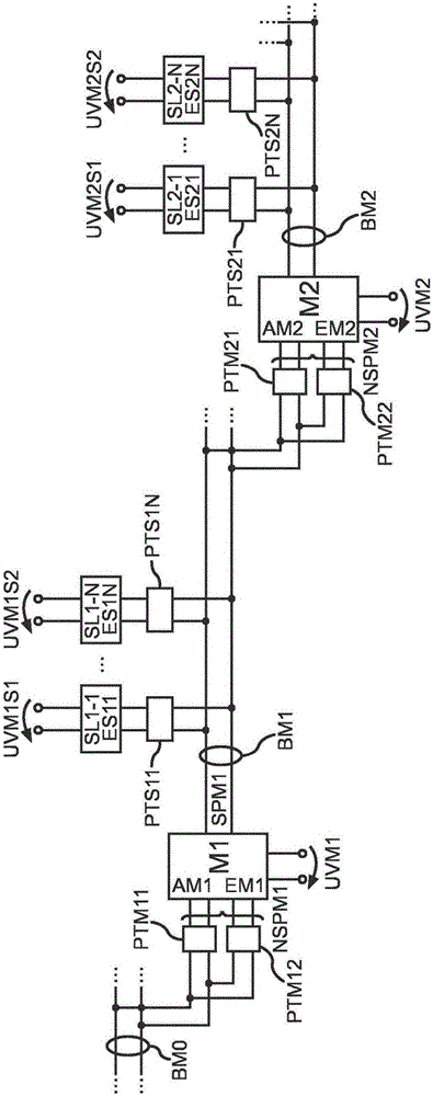
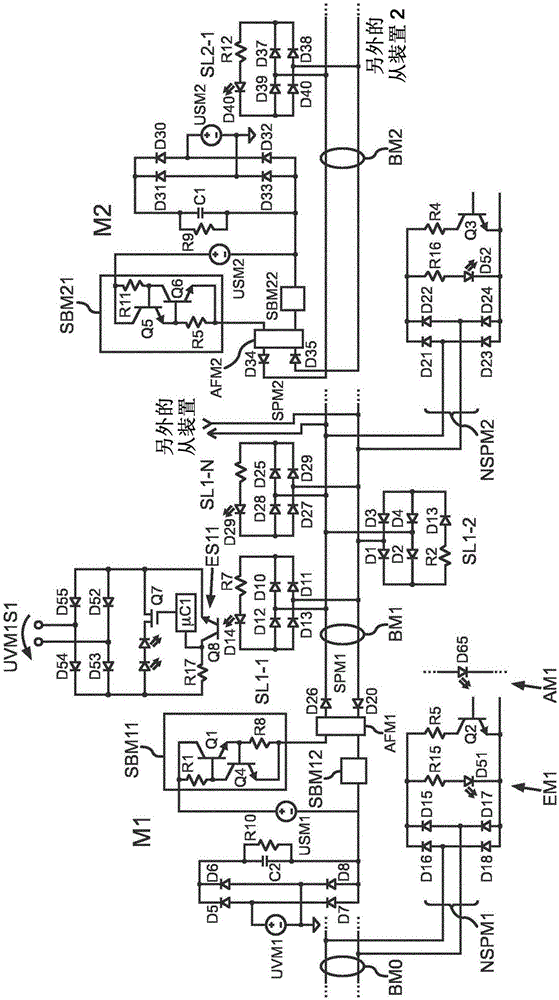
[0034] figure 1 An embodiment of a schematically represented circuit assembly according to the invention is shown. The circuit assembly includes a first main device M1 and a second main device M2. The master device M1 comprises a feed connection SPM1 adapted to apply control signals to the bus BM1. The master M1 additionally comprises a non-feed connection NSPM1 coupled to the bus BMO. The potential isolation device PTM11 is arranged between the bus BM0 and the input EM1 of the master M1. The potential isolation device PTM12 is arranged between the bus BM0 and the output AM1 of the master M1 . The master device M1 is connected to a voltage source UVM1 which may represent an alternating voltage source, for example a mains voltage. A plurality of slave devices SL1-1 and SL1-N are associated with a mast...


PUM


Abstract

The invention relates to a circuit assembly for operating at least one lighting means. The circuit assembly comprises at least one master device (M1); at least one slave device (SL1-1); and a bus system having at least one bus (BM1), by means of which bus system the at least one master device and the at least one slave device are coupled, wherein the bus is designed as a two-wire cable, the at least one master device has at least one feeding connection (SPM1) coupled to the bus and designed to place a control signal (USM1) on the bus, the at least one master device is coupled to a first voltage supply (UVM1), the at least one slave device (SL1-1) comprises a non-feeding connection coupled to the bus, the slave device (SL1-1) comprises a connection for at least one lighting means, a second voltage supply (UVM1S1), and a read-out device for reading out the control signal on the bus, the read-out device comprises a potential-isolating device (D14, Q8) and the connection for the at least one lighting means and the second voltage supply are provided on the side of the read-out device isolated from the bus with regard to potential.

Description

technical field [0001] The invention relates to a circuit arrangement for operating at least one lighting device having at least one master, at least one slave and a bus system with at least one bus, wherein at least one master and at least one slave are coupled to the bus system. Background technique [0002] The underlying lamp or lighting device is also called LE (=Light Engine), which may comprise an automation unit of the lighting system. These automation units may for example be light sensors which prevent switching on of the LE when there is sufficiently strong ambient light and automatically switch on the LE accordingly if the ambient light falls below a preset value. Furthermore, a motion sensor can also be integrated on the LE, which switches on the LE or changes its brightness if motion is detected in the target area, such as a moving person. [0003] However, in the case of some applications, for lighting reasons, it may be relatively reasonable to provide a re...

Claims


Application Information

Patent Timeline
Patent Type & Authority Applications(China)
IPC IPC(8): H05B37/02
CPCH05B47/18G06F13/4068H04L12/40019H05B47/115Y02B20/40H05B47/11
Inventor 克劳斯·菲舍尔马尔科·安特雷特赫尔穆特·恩德雷斯
Owner OSRAM GMBH
Why Eureka
Try Eureka