Respirator pipeline

A ventilator and pipeline technology, applied in the field of medical equipment, can solve problems such as safety hazards, damage, and ventilator pollution, and achieve the effects of ensuring airtightness, ensuring airtightness, and avoiding residues

Active Publication Date: 2016-11-16
成都欧赛医疗器械有限公司
View PDF11 Cites 5 Cited by
  • Summary
  • Abstract
  • Description
  • Claims
  • Application Information

AI Technical Summary

Problems solved by technology

[0002] In the process of medical assistance, ventilators are often used to help patients with assisted breathing, and during the use of the ventilator, condensed water will be generated in the breathing circuit, which will accumulate The condensed water will not only affect the delivery of oxygen, if the condensed water enters the patient's respiratory tract along the pipeline, it will cause breathing difficulties and bring danger to the patient
[0003] In order to solve this problem, at this stage, a water collection cup is installed in the middle of the air inlet pipe and the air outlet pipe of the breathing pipeline to collect the condensed water in the pipeline. It is at the lowest point of the pipeline, so the condensed water does not flow into the water collection cup in time and enters the patient's respiratory tract along the pipeline, causing the patient to have difficulty breathing or even block
[0004] In addition, since the water collection cup is connected in series with the ventilator pipeline through a tee, the tee joint is easy to fall off when external force is received, resulting in accidents
[0005] However, some patients require drug inhalation therapy while assisting breathing. If the drug is added to the ventilator pipeline through the ventilator, it is easy to cause internal pollution or even damage to the ventilator.
[0006] In order to increase the condensation effect and increase the contact surface, the current ventilator pipelines are all threaded tubes. However, some condensed water will remain at the bottom of each thread. If the residual condensed water is too much, it will easily enter the patient's respiratory tract along the pipeline, causing patients difficulty breathing or even blockage
During the actual operation, the medical staff need to shake regularly or erect the ventilator pipeline to discharge the residual condensed water at the bottom of the thread, which not only increases the workload of the medical staff, but also poses certain safety hazards

Method used


Image

  • Respirator pipeline
  • Respirator pipeline
  • Respirator pipeline

Examples


Embodiment Construction

[0041] In order to make the object, technical solution and advantages of the present invention clearer, the present invention will be further described in detail below in conjunction with the accompanying drawings.

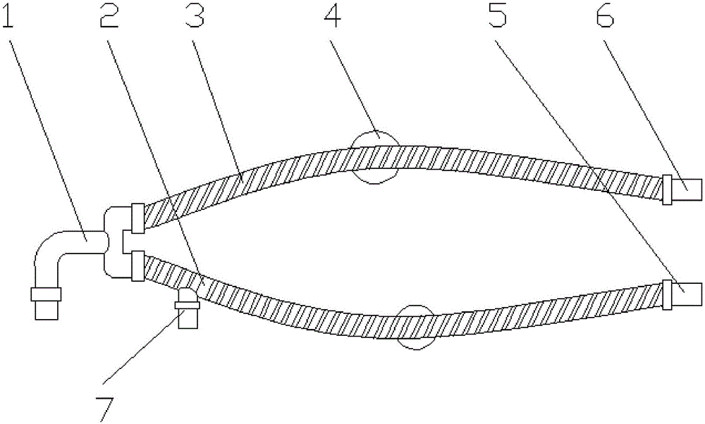
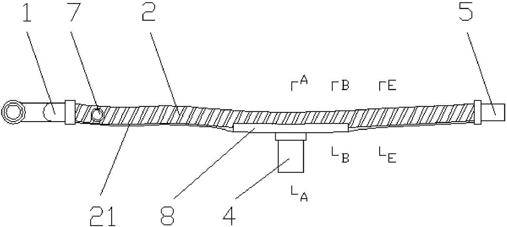
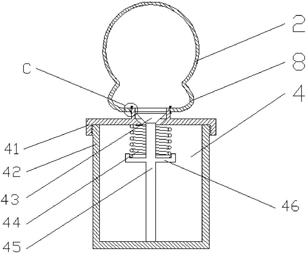
[0042] like Figure 1-9 As shown, a ventilator pipeline disclosed by the present invention includes a Y-shaped joint 1, an inhalation pipe 2, an exhalation pipe 3, and a water collection cup 4. Both the inhalation pipe 2 and the exhalation pipe 3 are threaded pipes, and the inhalation One end of the tube 2 is connected to a branch of the Y-shaped joint 1, the other end of the inspiratory tube 2 is provided with an inspiratory tube joint 5, one end of the exhalation tube 3 is connected to the other branch of the Y-shaped joint 1, and the other end of the exhalation tube 3 is set Exhalation pipe joint 6, two water collection cups 4, two water collection cups 4 communicate with the suction pipe 2 and the exhalation pipe 3 respectively, the inner sidewalls of the exha...


PUM


Abstract

The invention discloses a respirator pipeline, and belongs to the field of medical equipment. The respirator pipeline comprises a Y-shaped connector, an aspirating pipe, an exhaling pipe and two water collecting cups; the aspirating pipe and the exhaling pipe are both threaded pipes, the water collecting cups are communicated with the aspirating pipe and the exhaling pipe respectively, the inner side wall of the aspirating pipe and the inner side wall of the exhaling pipe are each provided with a water collecting ditch guiding water into the corresponding water collecting cup, the water collecting ditches are arranged in the axial direction, and the bottom of each water collecting ditch is lower than the thread bottom of the corresponding threaded pipe. The respirator pipeline can adjust the positions of the water collecting cups to be always located at the lowest part of the respirator pipeline, and collection of condensated water is guaranteed, and pipeline rupture and disengagement can be avoided; meanwhile, drugs can be prevented from being aspirated to contaminate a respirator; the condensated water can be prevented from being left at the thread bottoms, and the condensated water can completely flow into the water collecting cups.

Description

technical field [0001] The invention relates to a medical device, in particular to a ventilator pipeline. Background technique [0002] In the process of medical assistance, ventilators are often used to help patients with assisted breathing. During the use of the ventilator, condensation water will be generated in the breathing circuit. The accumulated condensation water will not only affect the delivery of oxygen, but if the condensation water goes along The tubing enters the patient's airway, causing breathing difficulties and putting the patient at risk. [0003] In order to solve this problem, at this stage, a water collection cup is installed in the middle of the air inlet pipe and the air outlet pipe of the breathing pipeline to collect the condensed water in the pipeline. It is at the lowest point of the pipeline, so the condensed water does not flow into the water collection cup in time and enters the patient's respiratory tract along the pipeline, causing the pati...

Claims


Application Information

Patent Timeline
Patent Type & Authority Applications(China)
IPC IPC(8): A61M16/08
CPCA61M16/08A61M16/0808
Inventor 刘岩刘帆张茂杰田永明
Owner 成都欧赛医疗器械有限公司
Why Eureka
Try Eureka