Optical fiber detection device for biological detection

A detection device and biological detection technology, applied in the direction of fluorescence/phosphorescence, optical waveguide coupling, material excitation analysis, etc., can solve the problems of system complexity, large volume, low yield, etc., to improve coupling efficiency and reduce signal-to-noise ratio , cost reduction effect

Inactive Publication Date: 2015-12-02
BEIJING SCITLION TECH
View PDF6 Cites 9 Cited by
  • Summary
  • Abstract
  • Description
  • Claims
  • Application Information

AI Technical Summary

Problems solved by technology

Traditional optical fiber biosensors use optical fibers as probes and optical information transmission, but still use optical separation components when collecting information, so the system is complex and bulky; at present, new optical fiber sensors have replaced traditional optical fiber sensors. The optical fiber detection device in the optical fiber sensor is composed of a tapered optical fiber and a single-multimode optical fiber coupler. Since this single-multimode optical fiber coupler is made of a single-mode optical fiber and a multi-mode optical fiber fusion tapered The cross-sectional area of ​​the single-mode fiber and the multi-mode fiber used are hundreds of times different, so the manufacturing process of the coupler is very difficult, the yield is very low, and the cost is very high, which is not conducive to mass production and market promotion of the product.

Method used


Image

  • Optical fiber detection device for biological detection

Examples


Embodiment Construction

[0019] The specific embodiments of the present invention will be described in further detail below in conjunction with the accompanying drawings.

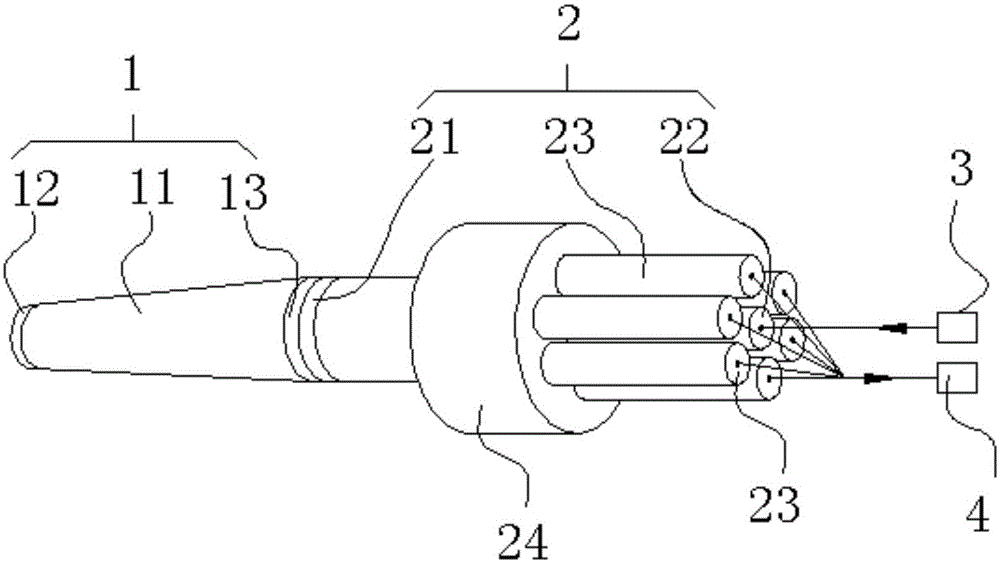
[0020] as attached figure 1 As shown, a fiber optic detection device for biological detection according to the present invention includes an optical fiber probe 1 and an optical fiber bundle assembly 2 connected to each other, and a laser 3 connected to the optical fiber bundle assembly 2 for emitting a laser beam, A fluorescence collection photoelectric receiver 4 connected to the fiber bundle assembly 2 and used for receiving photoelectric signals. Described optical fiber bundle assembly 2 is Y-type optical fiber bundle assembly, and described Y-type optical fiber bundle assembly comprises optical fiber bundle general end 21, and the single-mode optical fiber 22 that is respectively connected with optical fiber bundle general end 21, branch optical fiber 23; Wherein, described The laser beam emitted by the laser 3 is coupled to ...


PUM


Abstract

The invention relates to an optical fiber detection device for biological detection. The optical fiber detection device comprises an optical fiber probe, an optical fiber bundle assembly, a laser device and a fluorescence collection photoelectric receiver, wherein the optical fiber probe and the optical fiber bundle assembly are connected with each other, and the laser device and the fluorescence collection photoelectric receiver are connected with the optical fiber bundle assembly. The optical fiber bundle assembly is a Y-type optical fiber bundle assembly which comprises an overall optical fiber bundle end, a single-mode optical fiber and branch optical fibers, wherein the single-mode optical fiber and the branch optical fibers are connected with the overall optical fiber bundle end. The optical fiber detection device has the advantages that by the adoption of the optical fiber probe and the Y-type optical fiber bundle assembly, transmission of laser beams and collection and transmission of optical signals are completed; by connecting the single-mode optical fiber to the LD laser device, it is guaranteed that the mode of laser beams collected by the single-mode optical fiber is singular; through the conical optical fiber probe, the collection quantity of fluorescence signals is guaranteed; through the branch optical fibers of the Y-type optical fiber bundle assembly and the fluorescence collection photoelectric receiver, the coupling efficiency of optical signals is improved, the signal-to-noise ratio of the equipment is reduced, the structure of the equipment is simplified, and the cost is lowered.

Description

technical field [0001] The invention relates to the technical field of biological detection, in particular to the technology of using laser light to excite biological substances marked with fluorescent molecules to realize biological detection, and in particular to an optical fiber detection device for biological detection. Background technique [0002] Optical fiber is an abbreviation for optical fiber. It is a soft filament drawn from quartz glass or special plastic, and its structure is the core, cladding and coating from the inside to the outside. The refractive index of the cladding is slightly smaller than that of the core. According to the principle of total reflection in geometric optics, the light is bound in the core for transmission. Outside the cladding is a coating layer of 5-40 μm, whose function is to enhance the mechanical strength of the optical fiber and increase flexibility at the same time. There is usually a 100μm thick buffer layer or plastic layer on...

Claims


Application Information

Patent Timeline
Patent Type & Authority Applications(China)
IPC IPC(8): G01N21/64G02B6/42
Inventor 朱文华王琦吴迪杨双收龙峰魏秀珍
Owner BEIJING SCITLION TECH
Why Eureka
Try Eureka