A flushing system and flushing method for a filter tank body

A flushing system and filter technology, which is applied in separation methods, filtration separation, chemical instruments and methods, etc., can solve the problems of dirty tank flushing, stirring frame failure, ceramic plate wear, etc., to achieve good flushing effect and complete cleaning , running smoothly

Active Publication Date: 2019-01-11
安徽马钢罗河矿业有限责任公司
View PDF9 Cites 0 Cited by
  • Summary
  • Abstract
  • Description
  • Claims
  • Application Information

AI Technical Summary

Problems solved by technology

[0008] Aiming at the problem that the tank body of the existing filter machine is not flushed cleanly, causing wear of the ceramic plate and failure of the stirring frame, the invention provides a flushing system and a flushing method of the filter tank body

Method used


Image

  • A flushing system and flushing method for a filter tank body
  • A flushing system and flushing method for a filter tank body
  • A flushing system and flushing method for a filter tank body

Examples


Embodiment 1

[0044] In the prior art, the equipment has many deficiencies: one is that the flushing water on the left side and the flushing water on the right side are the same main pipe, and the two diversions cause obvious insufficient pressure, and the water pressure is not enough to clean the tank body; The existing flushing system installed on the right side of the unloading area can only flush several rows of ceramic plates, but the position between the rows of ceramic plates cannot be flushed; the third is the thin aluminum-plastic pipe installed in the original unloading area And it is short and cannot go deep into the tank body, resulting in poor effect; there is no flushing water installed at the crank arms of the four pairs of stirring brackets, causing the stirring screws to often fall off in actual production, resulting in a high frequency of major production accidents. The cleaning system of the existing ceramic filter is not perfect, the flushing effect is not good, and the c...

Embodiment 2

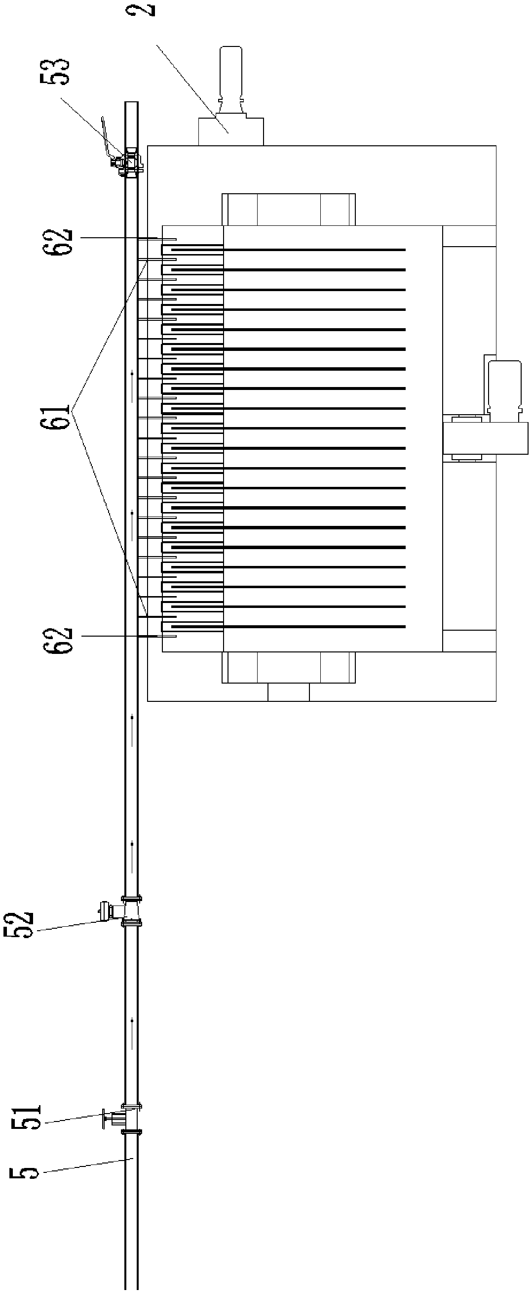
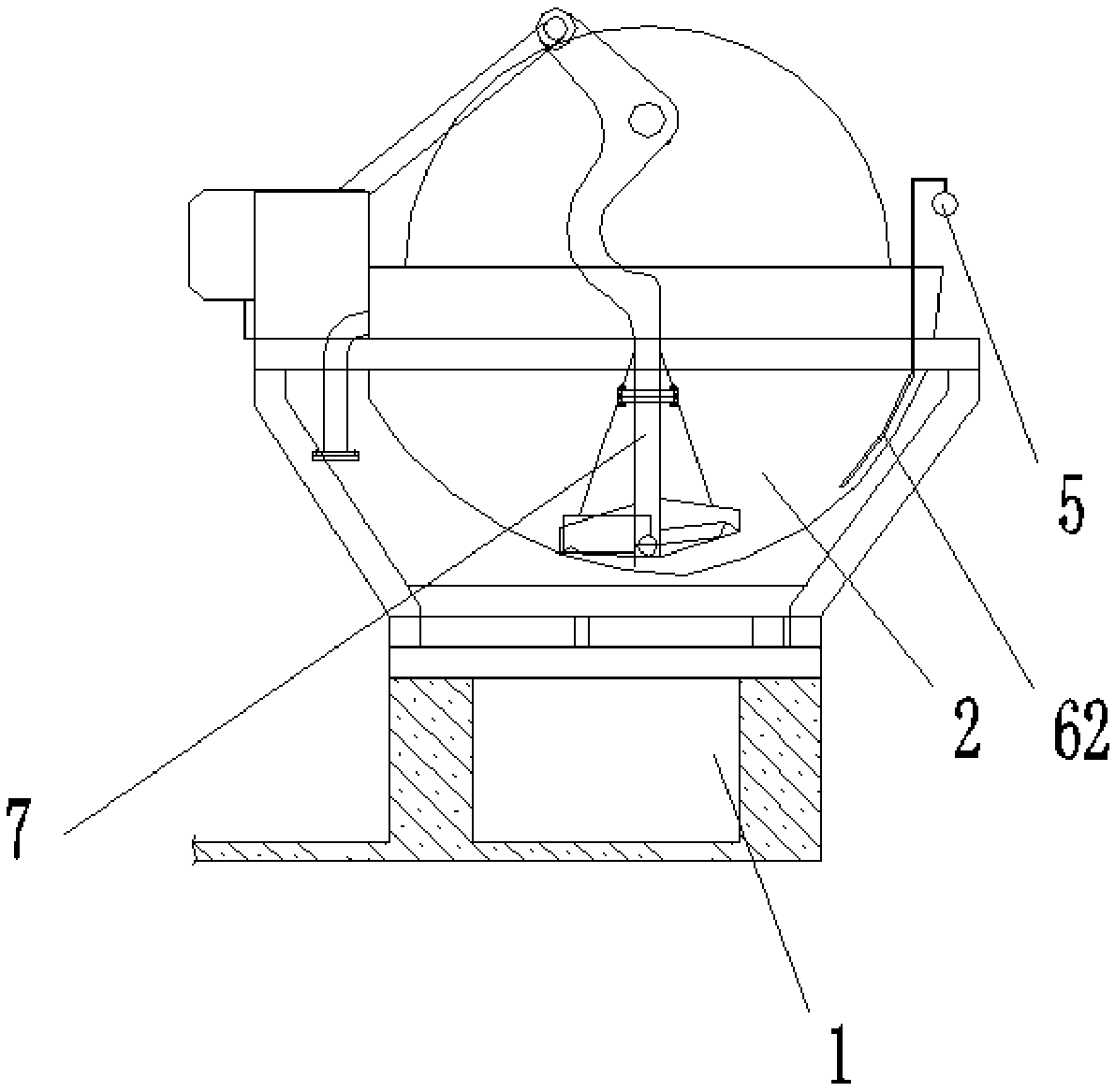
[0051] Embodiment 2 is basically the same as Embodiment 1, the difference is that, as Figure 4 As shown, the flushing water pipe I61 and the flushing water pipe II62 extend into the ceramic filter 2, and both the flushing water pipe I61 and the flushing water pipe II62 include a flushing inlet 63 and then pass through a flushing flat pipe 65, a flushing vertical pipe 66, and a flushing elbow 67 to reach a flushing outlet 64 , the flushing elbow 67 in the lower part is a bent concave shape, and the curvature is compared with different types of filter tanks on site, and the size is determined and uniformly manufactured, so as to fully ensure that it fits the tank and does not affect the operation of the stirring frame 7 , the flushing outlet 64 at the end of the flushing water pipe I61 and the flushing water pipe II62 is a flat oval water outlet, and the ends are made flat and small to increase the momentum and facilitate flushing. Installing at 7 places on the left and right st...

Embodiment 3

[0053] Embodiment 3 is basically the same as Embodiment 1, the difference is that an inlet gate valve 51 is also provided on the water inlet pipeline 5 for independent control, and a blowdown valve 53 is arranged at the tail of the water inlet pipeline 5, and when the water inlet pipeline 5 is blocked, Carry out drainage. Both ends can be controlled independently, which is convenient for the staff to maintain and open the pipeline.


PUM


Abstract

The invention discloses a filter tank flushing system and a flushing method, and belongs to the field of concentrate dewatering. The filter tank flushing system comprises a ceramic filter, a dewatering barrel, a left flushing water pipe and a right flushing water pipe, wherein the ceramic filter and the dewatering barrel are arranged on a device foundation platform. A water inlet pipeline is arranged beside a right unloading area of the ceramic filter and comes out of an outer ring water header of a filter system, and a plurality of flushing water pipes are led into one side of the water inlet pipeline reaching the ceramic filter and used for flushing a tank between ceramic plates of the ceramic filter and mixing frames on two sides of the ceramic filter. Different flushing water pipes I and flushing water pipes II arranged on two sides are used for conveniently flushing the tank and the mixing frames respectively in a targeted manner, the flushing water pipes can penetrate into the tank and perform flushing, and flushing effects are good, so that wear resistance of the ceramic plates and stable running of the mixing frames are realized.

Description

technical field [0001] The invention relates to the field of concentrate dehydration, and more specifically relates to a flushing system and a flushing method for a tank body of a filter. Background technique [0002] Ceramic filter is a high-efficiency solid-liquid separation device. At present, the product has been widely used in major mining enterprises such as iron concentrate, copper concentrate, lead concentrate, aluminum concentrate, gold concentrate, and fluorite mine. filter. The working principle of the ceramic filter is: under the action of the pressure difference, when the suspension passes through the filter medium, the particles are trapped on the surface of the medium to form a filter cake, while the liquid flows out through the filter medium to achieve the purpose of solid-liquid separation. [0003] During the operation of the ceramic filter, the ceramic filter needs to be cleaned regularly. The cleanliness of the tank plays a decisive role in the operatio...

Claims


Application Information

Patent Timeline
Patent Type & Authority Patents(China)
IPC IPC(8): B01D33/17B01D33/48B01D33/80
CPCB01D33/17B01D33/48B01D33/80
Inventor 吴新义徐宝金张志达曹坤张浩刘小勇钟国强左金权
Owner 安徽马钢罗河矿业有限责任公司
Why Eureka
Try Eureka