Automatic stamping device

A stamping device and automatic technology, applied in the field of stamping machines, can solve the problems of high risk factor, low work efficiency, high labor intensity of operators, etc., and achieve the effect of accurate positioning

Inactive Publication Date: 2016-11-16
安庆晟扬精密机械零部件有限公司
View PDF10 Cites 13 Cited by
  • Summary
  • Abstract
  • Description
  • Claims
  • Application Information

AI Technical Summary

Problems solved by technology

The so-called double action means that the press has two sliders, which are divided into an inner slider and an outer slider. The inner slider drives the punch or die of the mold, and the outer slider drives the blankholder on the mold. When the blank holder first moves to press the edge of the steel plate, the inner slider moves to stretch again. In the factory, the stamping machine often requires the operator to place the parts to be processed on the side. The operator has high labor intensity, high risk factor and low work efficiency.

Method used


Image

  • Automatic stamping device
  • Automatic stamping device
  • Automatic stamping device

Examples


Embodiment Construction

[0019] The embodiments of the present invention will be described in detail below with reference to the accompanying drawings, but the present invention can be implemented in many different ways defined and covered by the claims.

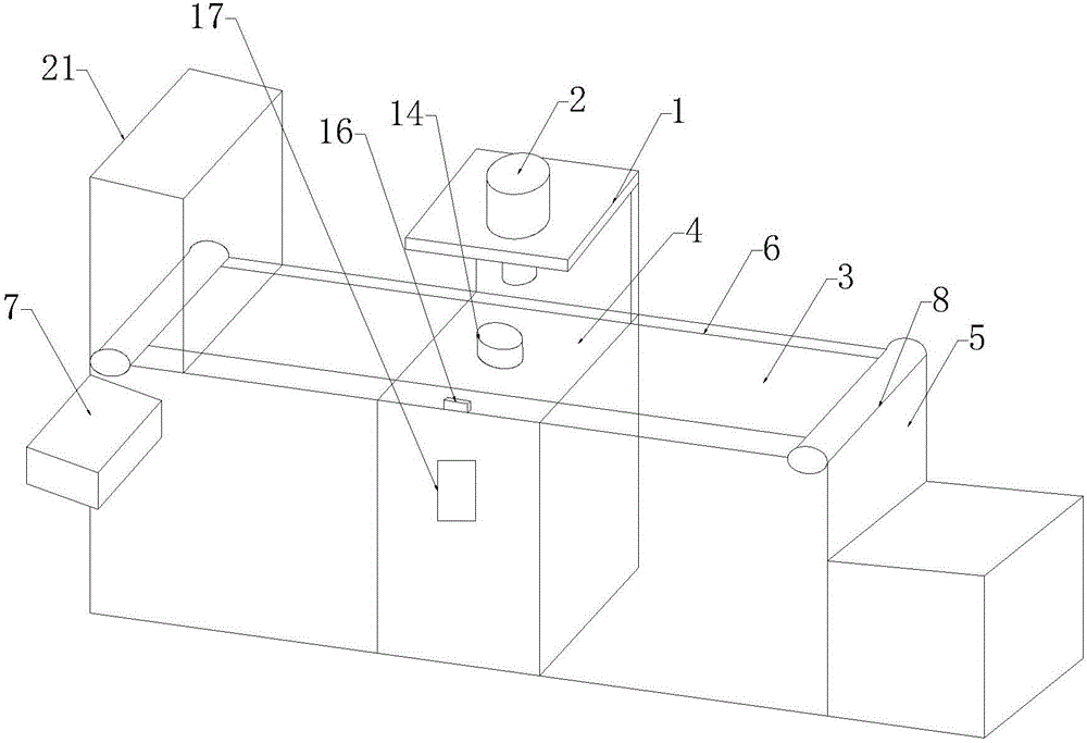
[0020] As shown in the accompanying drawings, an automatic stamping device includes a support 1, a stamping machine 2 installed on the support 1, a transport device 3 located below the stamping machine 2, and a collection tank 4 at the outlet of the transport device 3. The transport device 3 includes The workbench 4 directly below the punching machine 2, the transport bracket 5, the power unit installed on the transport bracket 5 and the conveyor belt 6, the power unit includes a servo motor 7 installed on the transport bracket 5, and a rotary motor 7 mounted on the transport bracket 5. The shaft 8 on the end and the sprocket 9 installed on the two ends of the shaft 8, the conveyor belt 6 includes a chain plate 11 with pin shaft jacks 10 on both side...


PUM


Abstract

The invention discloses an automatic punching device, which comprises a bracket, a punching machine installed on the bracket, a transportation device located under the punching machine, and a collection tank located at the outlet of the transportation device. Bracket, power unit and conveyor belt installed on the delivery bracket, the power unit includes a servo motor installed on the delivery bracket, rotating shafts installed on both ends of the delivery bracket and sprockets installed on both ends of the shaft, and the conveyor belt includes Both sides of the chain plate are equipped with pin shaft sockets, the pin shaft connecting the chain plate and the chains installed on the other two sides of the chain plate. The chain plate is connected by the pin shaft to form an endless conveyor belt. There are several through holes through the end surface on the board. In the present invention, an automatic feeding device is provided to realize automatic feeding. The feeding speed matches the speed of stamping parts to realize automatic punching; the conveyor belt ensures that the parts are in the process of transportation. Positioning accuracy.

Description

technical field [0001] The invention belongs to the technical field of stamping machines, in particular to an automatic stamping device. Background technique [0002] The punching machine drives the flywheel through the motor, and through the clutch, the transmission gear drives the crank linkage mechanism to move the slider up and down, and drives the drawing die to form the steel plate. The so-called double action means that the press has two sliders, which are divided into an inner slider and an outer slider. The inner slider drives the punch or die of the mold, and the outer slider drives the blankholder on the mold. When the blank holder first moves to press the edge of the steel plate, the inner slider moves to stretch again. In the stamping machine in the factory, the operator often needs to place the parts to be processed aside. The labor intensity of the operator is high, the risk factor is high, and the work efficiency is low. Contents of the invention [0003] ...

Claims


Application Information

Patent Timeline
Patent Type & Authority Applications(China)
IPC IPC(8): B21D22/22B21D43/12B21D45/04
CPCB21D22/22B21D43/027B21D43/12B21D45/003B21D45/04
Inventor 汪海峰
Owner 安庆晟扬精密机械零部件有限公司
Why Eureka
Try Eureka