Annular water curtain device

A water curtain and ring-shaped technology, applied in metal processing machinery parts, maintenance and safety accessories, metal processing equipment, etc., can solve the problems of difficult product quality assurance, narrow cooling range, uneven cooling, etc., to achieve no dead angle cooling, Good cooling effect and simple structure

Inactive Publication Date: 2016-11-16
BEIJING JINGDIAO GRP CO LTD
View PDF7 Cites 7 Cited by
  • Summary
  • Abstract
  • Description
  • Claims
  • Application Information

AI Technical Summary

Problems solved by technology

This cooling method has shortcomings such as small flow rate, narrow cooling range, and uneven cooling. It can still meet the requirements for processing that does not require high cooling, but for occasions that require high cooling, such as grinding heads in grinding processing. In the case of circular motion, the large grinding head only depends on a few nozzles for cooling, so there will inevitably be many dead angles, and the quality of the processed products is difficult to guarantee

Method used


Image

  • Annular water curtain device
  • Annular water curtain device
  • Annular water curtain device

Examples


Embodiment Construction

[0011] The present invention will be further described in detail below in conjunction with the accompanying drawings and specific embodiments.

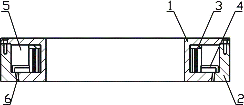
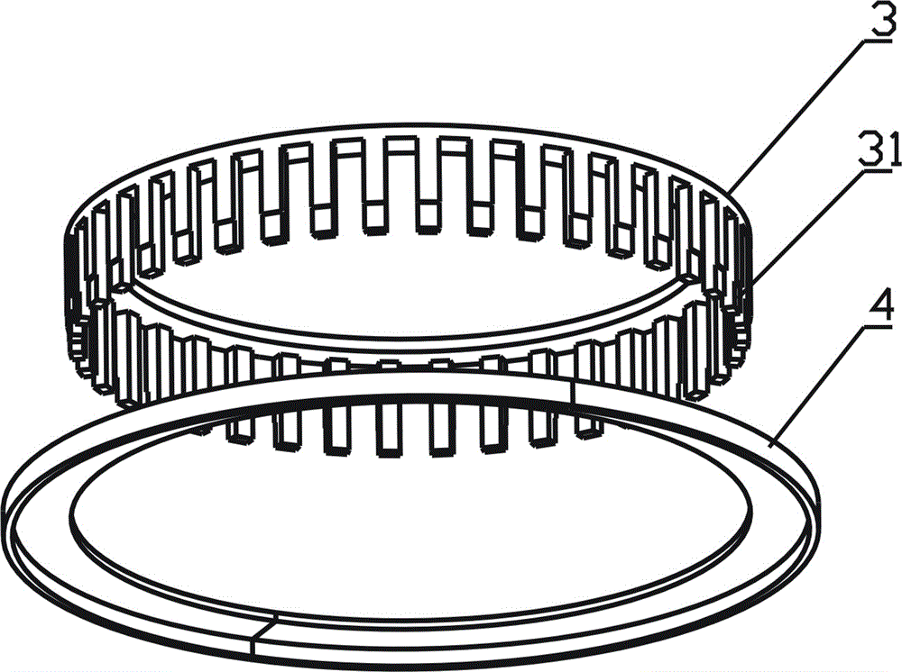
[0012] Such as figure 1 As shown, an annular water curtain device of the present invention is composed of a water curtain inner ring 1 , a water curtain outer ring 2 , a slow flow plate inner ring 3 and a slow flow plate outer ring 4 . The water curtain inner ring 1 and the water curtain outer ring 2 are fixedly installed together to form an annular water holding space 5 inside, wherein the radial section of the water curtain inner ring 1 is an inverted I-shaped structure, and the outer edge of the bottom is a slope, and The slope of the water curtain outer ring 2 cooperates to form an annular tapered water outlet 6 with a certain width, which can make the formed water curtain have a certain taper.

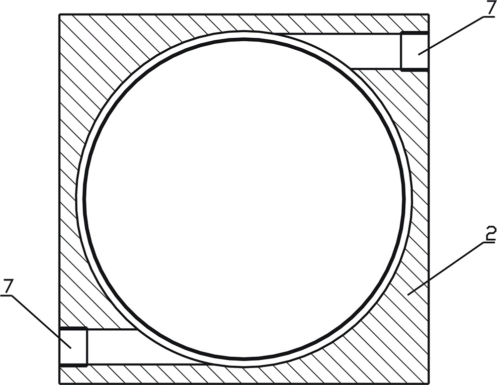
[0013] Such as figure 2 As shown, two water inlets 7 leading to the water holding space are diagonally distributed on the outer ring ...


PUM


Abstract

The invention belongs to the technical field of mechanical processing, and in particular relates to an annular water curtain device. The device comprises inner rings of a water curtain, outer rings of the water curtain, inner rings of flowing slowing plates and outer rings of the flowing slowing plates, wherein the inner rings, equipped with central mounting holes, of the water curtain, are integrally mounted to the outer rings of the water curtain; annular water storing spaces are formed in the inner rings of the water curtain; annular tapered water outlets are formed in the bottom parts of the water storing spaces; water inlets which communicate with the water storing spaces are formed in the outer rings of the water curtain; the inner rings of the flowing slowing plates are of an annular comb shaped structure, and pressing slots are formed in the lower ends of comb teeth; the sections of the outer rings of the flowing slowing plates are bent, and the outer rings of the flowing slowing plates sleeve the corresponding pressing slots of the inner rings of the flowing slowing plates and are positioned in the corresponding water storing spaces together with the inner rings of the flowing slowing plates. The annular water curtain device is simple in structure, can form a complete, uniformly-distributed and non-rotating tapered curtain type water curtain, so that a cutting cutter can be cooled in 360 degrees without any dead angle, and as a result, the cooling effect is good.

Description

technical field [0001] The invention belongs to the technical field of mechanical processing, in particular to an annular water curtain device for cooling machine tool processing. Background technique [0002] During machining, machine tools mostly use cooling nozzles to spray coolant in the machining direction to cool cutting tools and workpieces. This cooling method has shortcomings such as small flow rate, narrow cooling range, and uneven cooling. It can still meet the requirements for processing that does not require high cooling, but for occasions that require high cooling, such as grinding heads in grinding processing. In the case of circular motion, the large grinding head is cooled only by a few nozzles, so there will inevitably be many dead angles, and the quality of the processed products is difficult to guarantee. Contents of the invention [0003] The object of the present invention is to overcome the disadvantages of the prior art, and provide an annular wate...

Claims


Application Information

Patent Timeline
Patent Type & Authority Applications(China)
IPC IPC(8): B23Q11/10
CPCB23Q11/10
Inventor 贾军政栗瑞庆
Owner BEIJING JINGDIAO GRP CO LTD
Why Eureka
Try Eureka