Automatic cutting equipment

An automatic cutting and equipment technology, which is applied in metal processing equipment, grinding/polishing equipment, cleaning methods using gas flow, etc., can solve problems such as environmental pollution, human body injury caused by cutting machines, and achieve convenient operation and low production cost. The effect of low, short-structured answers

Inactive Publication Date: 2016-11-16
SUZHOU HUANING MACHINERY MFG
View PDF7 Cites 7 Cited by
  • Summary
  • Abstract
  • Description
  • Claims
  • Application Information

AI Technical Summary

Problems solved by technology

[0002] At present, there are many kinds of cutting machines on the market, such as steel cutting machines, wood cutting machines, membrane cutting machines, etc., but the cutting machines will inevitably produce some dust and unpleasant smell during the cutting process , some dust is scattered on the floor of the workshop, and some dust with relatively small particles is floating in the air, which not only pollutes the environment, but also causes great harm to the body of the person who uses the cutting machine. The surface of the cutting product is cleaned manually. Therefore, it is necessary to design a cutting machine with environmental protection function, which can effectively reduce environmental pollution and harm to the human body, and can clean the surface of the cutting product.

Method used


Image

  • Automatic cutting equipment

Examples


Embodiment Construction

[0015] In order to make the object, technical solution and advantages of the present invention more clear, the present invention will be further described in detail below in conjunction with the examples. It should be understood that the specific embodiments described here are only used to explain the present invention, not to limit the present invention.

[0016] The application principle of the present invention will be described in detail below in conjunction with the accompanying drawings.

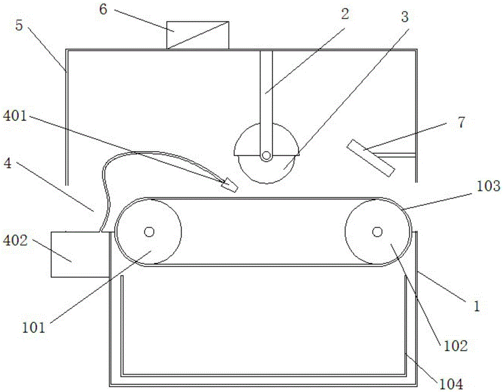
[0017] Such as figure 1 Shown, a kind of automatic cutting equipment comprises carrier 1, lifting mechanism 2, cutting wheel 3 driven by motor, water spray assembly 4, dustproof cover 5, air blower 6 and plasma blower 7; The work of described carrier 1 There are several through holes (not shown in the figure) on the table, and the work table is a conveyor belt 103 driven by a driving wheel 101 and a driven wheel 102, which is used to send objects to be cut from the entrance of the car...


PUM

PropertyMeasurementUnit
diameteraaaaaaaaaa

Abstract

The invention discloses automatic cutting equipment. The equipment comprises a carrying table, a lifting mechanism, a cutting wheel driven by a motor, a water spray assembly, a dust cover, an air blower and a plasma fan, wherein a plurality of through holes are formed in the working table top of the carrying table; the working table surface is a conveying belt driven by a driving wheel and a driven wheel; a waste storage box is arranged in the carrying table; the cutting wheel is driven by the lifting mechanism to move up and down; the lifting mechanism is mounted at an inlet of the carrying table; the water spray assembly comprises a spray head and a water pump, the working surface of the spray head faces the contact position of the cutting wheel and the working table top, and the water pump is connected with the spray head by the aid of a guide pipe; the dust cover covers the carrying table; the air blower is arranged at the top of the dust cover, and the working surface of the air blower directly faces the working table top; and the plasma fan is mounted at an outlet of the carrying table, and the working surface of the plasma fan directly faces the working table top. The equipment is simple in structure, convenient to use and capable of effectively removing dust and reducing environmental pollution and damage to human bodies.

Description

technical field [0001] The invention belongs to the field of cutting machines, and in particular relates to an automatic cutting device. Background technique [0002] At present, there are many kinds of cutting machines on the market, such as steel cutting machines, wood cutting machines, membrane cutting machines, etc., but the cutting machines will inevitably produce some dust and unpleasant smell during the cutting process , some dust is scattered on the floor of the workshop, and some dust with relatively small particles is floating in the air, which not only pollutes the environment, but also causes great harm to the body of the person who uses the cutting machine. The surface of the cutting product is cleaned manually. Therefore, it is necessary to design a cutting machine with an environmental protection function, which can effectively reduce environmental pollution and damage to the human body, and can clean the surface of the cutting product. Contents of the inven...

Claims


Application Information

Patent Timeline
Patent Type & Authority Applications(China)
IPC IPC(8): B24B27/06B24B55/06B08B5/02B01D47/06
CPCB24B27/06B01D47/06B08B5/02B24B55/06
Inventor 钱海萍
Owner SUZHOU HUANING MACHINERY MFG
Why Eureka
Try Eureka