Vacuum screen printing machine hole plugging pad plate jig and hole plugging method thereof

A technology for a screen printing machine and a backing plate, which is applied in the direction of screen printing machine, printing machine, rotary printing machine, etc., can solve the problems of cumbersome processing method of printing platen, increase cost, reduce efficiency, etc., and achieve simple structure and cost. low, high efficiency

Inactive Publication Date: 2016-11-16
昆山晟丰精密机械有限公司
View PDF7 Cites 3 Cited by
  • Summary
  • Abstract
  • Description
  • Claims
  • Application Information

AI Technical Summary

Problems solved by technology

[0003] The top surface of the printing platen in the traditional vacuum screen printing machine is engraved with grooves, which assist the above-mentioned grooves to exhaust when vacuuming, and in addition to ensure the sufficient length of the table to support the scraper. The processing method of the platen is cumbersome, and grooves need to be drawn on the su...

Method used


Image

  • Vacuum screen printing machine hole plugging pad plate jig and hole plugging method thereof
  • Vacuum screen printing machine hole plugging pad plate jig and hole plugging method thereof

Examples


Embodiment 1

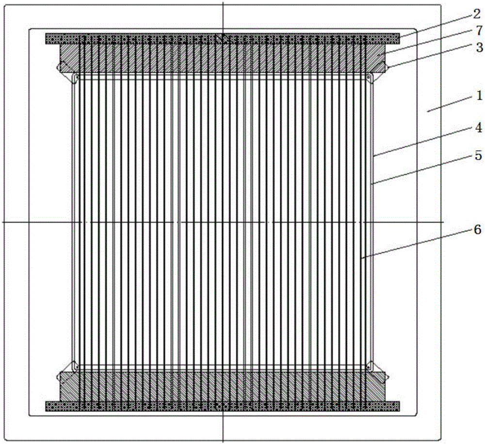
[0032] Embodiment 1 discloses a vacuum screen printing machine plug hole backing plate fixture, which is used in the plug hole printing process of the vacuum screen printing machine to prevent the ink in the hole from being depressed under the action of vacuum negative pressure when the hole is plugged .

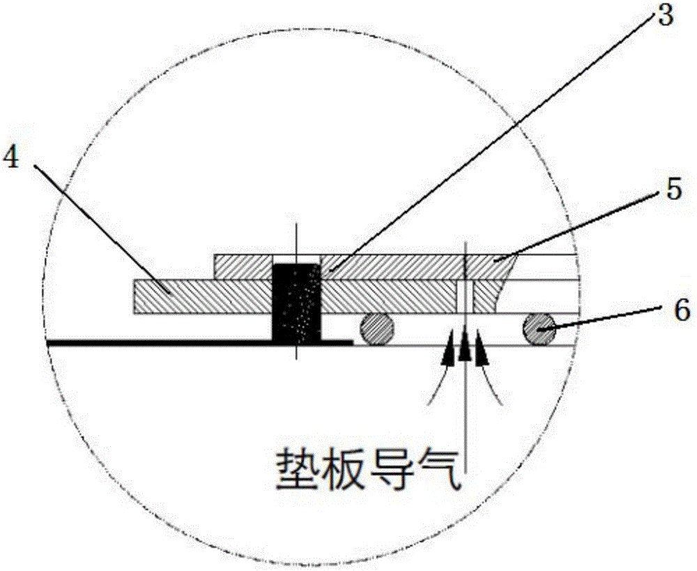
[0033] The structure of the fixture is as Figure 1-2 As shown, the jig is mainly used on the printing platen 1, the above-mentioned printing platen 1 is arranged in the printing chamber of the vacuum screen printing machine, and the two ends of the above-mentioned printing platen 1 are provided with double-sided adhesive tape 2, The above-mentioned double-sided adhesive tape 2 is arranged on the front and rear ends of the above-mentioned printing platen 1. In this embodiment, the positions of the front and rear ends of the above-mentioned printing platen 1 are based on the operator's work position. There are several aluminum pads 6 arranged between the two, and the above-m...

Embodiment 2

[0040] The vacuum screen printing machine plug hole backing plate jig disclosed in embodiment 2 is basically the same in structure as the jig in embodiment 1, the difference is that in embodiment 2, the aluminum spacer 6 is fixed on the above-mentioned printing platen 1 The method is different. In Embodiment 2, a number of aligned aluminum bar slots are provided at both ends of the above-mentioned printing platen 1 , and the distance between the above-mentioned aluminum bar slots is 10-15 mm.

[0041] The above-mentioned aluminum pads 6 are directly engaged between the above-mentioned aluminum strip slots, and the aluminum pads 6 are equally spaced on the above-mentioned printing platen 1 to form a printing area on the above-mentioned printing platen 1 .

[0042] In other embodiments, the distance between the above-mentioned aluminum pads 6 can be improved according to actual design needs, which is not limited here.

Embodiment 3

[0044] A kind of plug hole method is disclosed in embodiment 3, comprises the following steps:

[0045] Step 1. Paste the double-sided tape on the front and rear ends of the printing plate, and then evenly arrange the aluminum pads between the above-mentioned double-sided tapes according to the spacing of 10-15mm. The aluminum pads are perpendicular to the above-mentioned double-sided tapes on the horizontal plane. Adhesive tape, the above-mentioned aluminum pads form the printing area, and the left and right sides of the printing area are 5mm smaller than the two sides of the air guide plate.

[0046] Step 2. Place the air guide plate flatly on the aluminum pad, and secure the four corners of the above air guide plate with double-sided pins.

[0047] Step 3. During the printing operation, place the PCB board in the above-mentioned double-sided pins for positioning. When replacing different types of PCB boards, you only need to replace the above-mentioned air guide pad.

[0048...


PUM


Abstract

The invention discloses a vacuum screen printing machine hole plugging pad plate jig. The vacuum screen printing machine hole plugging pad plate jig comprises a printing table plate and an air guide pad plate; the printing table plate is arranged in a printing cavity of a vacuum screen printing machine, a plurality of aluminum pad strips are arranged on the printing table plate, and a printing area is formed by the aluminum pad strips; a plurality of air guide holes are formed in the air guide pad plate, the air guide pad plate is placed on the aluminum pad strips, the four corners of the air guide pad plate are fixed through double-face pins, and a PCB is sleeved with the double-face pins to be positioned; the air guide pad plate is supported by the aluminum pad strips, an air guide channel is formed between every two aluminum pad strips, air enters the air guide holes from the air guide channels, and the pressure difference of the two faces of the PCB is removed. Compared with an existing printing table plate adopting a special air guide pad plate or provided with an air guide groove, the jig is simple in structure, convenient to use and low in cost, the jig is shared by PCBs of different types, efficiency is high, and operation is convenient; and the jig can further be directly used in common with a non-vacuum hole plugging air guide pad plate.

Description

technical field [0001] The invention relates to the field of vacuum screen printing, in particular to a jig for a plug hole backing plate of a vacuum screen printing machine and a hole plugging method thereof. Background technique [0002] PCB board plug hole printing is to form a support in the original hole, and then copper plating, improve the contact area and flatness of the pad, and enhance the reliability of welding. In order to solve the occurrence of bulging, depression or discontinuity in traditional screen printing, a vacuum screen printing plug hole printing device is used to put the PCB board into the vacuum chamber. After the vacuum unit is evacuated, it is printed by the printing device in the vacuum chamber. , After scraping off the ink, open the vacuum chamber and take out the PCB board. [0003] The top surface of the printing platen in the traditional vacuum screen printing machine is engraved with grooves, which assist the above-mentioned grooves to exhau...

Claims


Application Information

Patent Timeline
IPC IPC(8): B41F15/36B41F15/34
CPCB41F15/36B41F15/34
Inventor 陈士丰祝波王勇
Owner 昆山晟丰精密机械有限公司
Why Eureka
Try Eureka