Basket type safe seat with seat belt assembly
A safety seat and safety belt technology, which is applied to vehicle seats, child seats, vehicle parts, etc., can solve the problems of unfavorable organs, failure to ensure the safety of passengers, fainting and even intracranial hemorrhage, and achieve the effect of convenient use
- Summary
- Abstract
- Description
- Claims
- Application Information
AI Technical Summary
Problems solved by technology
Method used
Image

Examples
Embodiment Construction
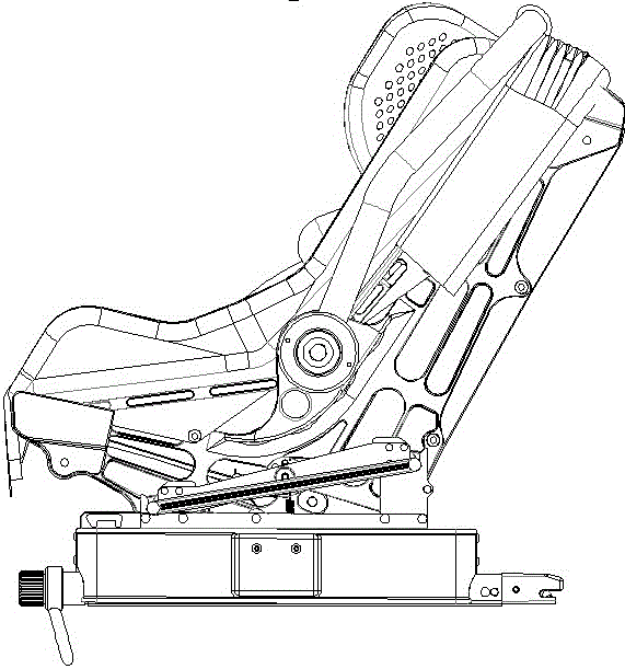
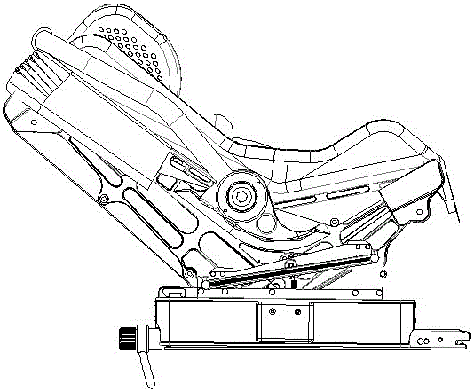
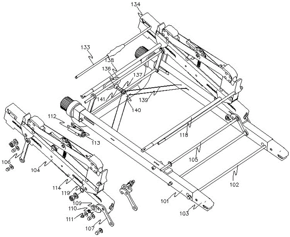
[0055] The specific embodiment of the present invention will be further described in detail below in conjunction with the accompanying drawings: the basket-type safety seat with safety belt assembly includes a base assembly 1 and a basket assembly 2, and the bottom surface of the basket assembly is provided with two connecting pins at the front and rear, and the basket The connecting pin of the assembly is installed on the base assembly, the base assembly includes the base pipe frame assembly and the energy absorbing assembly, the base pipe frame assembly includes two parallel square tubes 101, and the two square tubes are connected by at least two The shaft 102 is fixedly connected, and the tails of the pipes on all sides are respectively equipped with ISOFIX connection joints 103; the energy-absorbing assembly includes two parallel buffer slide bars 104, and the two parallel buffer slide bars 104 are fixed by two or more rotating shafts 105 connection, the buffer slide bar 10...
PUM
 Abstract
Description
Claims
Application Information
 - Generate Ideas
- Intellectual Property
- Life Sciences
- Materials
- Tech Scout
- Unparalleled Data Quality
- Higher Quality Content
- 60% Fewer Hallucinations
Browse by: Latest US Patents, China's latest patents, Technical Efficacy Thesaurus, Application Domain, Technology Topic, Popular Technical Reports.
© 2025 PatSnap. All rights reserved.Legal|Privacy policy|Modern Slavery Act Transparency Statement|Sitemap|About US| Contact US: help@patsnap.com