
Deoiling device

An oil tank and oil rod technology, which is used in grease/oily substance/float removal devices, adsorbed water/sewage treatment, liquid separation, etc., can solve the problem of difficult to control the recovery ratio, easy blocking of filters, and improper waste oil recovery and treatment. and other problems to achieve the effect of reducing friction and improving efficiency

Active Publication Date: 2016-11-16
ANYANG CHANGMING ENVIRONMENTAL PROTECTION EQUIP CO LTD
View PDF4 Cites 4 Cited by
  • Summary
  • Abstract
  • Description
  • Claims
  • Application Information

AI Technical Summary

Problems solved by technology

[0002] The oil-water separation of oily wastewater is used in many fields, and the waste oil recovery and treatment are improper, causing environmental pollution
However, after separating the oil and water, it is necessary to recover the oil floating on the upper layer. During the recovery process, it is difficult to control the recovery ratio, that is, it is difficult to determine the oil-water interface, especially when the oil content fluctuates, the oil-water interface will change with the oil content. Changes and floats, it is difficult to meet the requirements with a fixed oil outlet or oil skimmer
The filter screen of the filter device used in the traditional process is easy to be blocked. When cleaning the dirty oil of the filter screen, the oily wastewater in the oily wastewater pool needs to be discharged, and then the filter screen is cleaned. In addition, the oil-water separation of the traditional oil-water separation device is not complete, and it can only rely on oil-water Density removes part of the dirty oil, but it is difficult to remove the dirty oil suspended in water or sinking at the bottom, and it requires manual oil skimming, which is labor-intensive and other disadvantages

Method used


Image

  • Deoiling device
  • Deoiling device
  • Deoiling device

Examples


Embodiment Construction

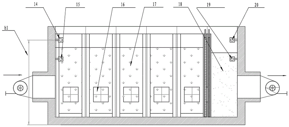
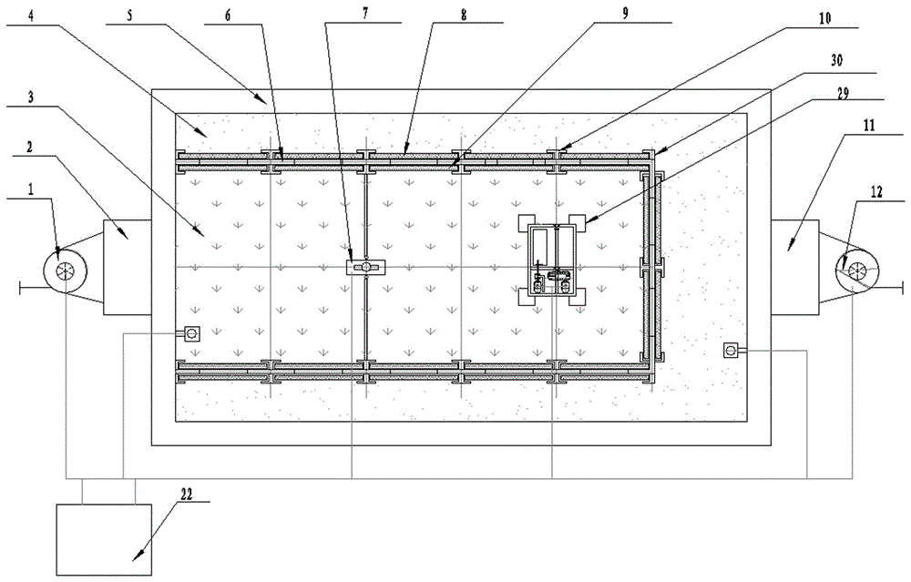
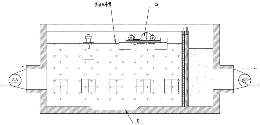
[0025] Such as Figure 1 to Figure 4 As shown, an oil-water separation device, the oil-water separation device includes a box body I5, a box body II6 is arranged in the box body I5, and the box body I5 and the box body II6 have no common wall, so that the box body II6 forms oily waste The water tank 3 and the tank I5 form a clean water tank 4, and an oily waste water 17 channel is set between the water inlet and the oily waste water tank 3, and the oily waste water 17 enters the oily waste water tank 3 through the channel.

[0026] When the tank body II6 is installed in the tank body I5, the tank body I5 and the tank body II6 have a common wall on the side of the water inlet, and the oily wastewater 17 enters the oily wastewater tank 3 from the water inlet.

[0027] Channels are set on the wall of the box body II6 not shared with the box body I5, and channels 30 are set on the other walls of the box body II6, so that the oily waste water tank 3 and the clean water tank 4 are c...


PUM


Abstract

A deoiling device comprises an oily wastewater tank and a clear water tank, wherein the oily wastewater tank is provided with a water inlet; the clear water tank is provided with a water outlet; a waste oil collecting device is arranged at the upper part of the oily wastewater tank; the deoiling device is characterized in that the oily wastewater tank is connected with the clear water tank through a channel; a filter screen membrane sliding rail is arranged on one side of the channel; a filter screen membrane is arranged on the channel; the filter screen membrane is provided with a filter screen membrane sliding frame matched with the sliding rail; the filter screen membrane sliding frame is matched with the filter screen membrane sliding rail to form a sliding rail pair. According to a scheme 1, when the filter screen membrane is cleaned, a water inlet pump and a water outlet pump are required to be turned off, and water in the oily wastewater tank and the clear water tank is not required to be drained; however, according to a scheme 2 and a scheme 3, when the filter screen membrane is cleaned, the water inlet pump and the water outlet pump work normally without influencing normal working of whole equipment, ultrasonic crude oil demulsifying equipment mounted in a ridged tank at the bottom of the oily wastewater tank demulsifies dirty oil suspended in water or sinking at the bottom of the oily wastewater tank, and the dirty oil floats to the water surface so as to remove the dirty oil.

Description

technical field [0001] The invention relates to the field of environmental protection, in particular to an oil removal device. Background technique [0002] The oil-water separation of oily wastewater is used in many fields, and the waste oil recovery and treatment are improper, causing environmental pollution. However, after separating the oil and water, it is necessary to recover the oil floating on the upper layer. During the recovery process, it is difficult to control the recovery ratio, that is, it is difficult to determine the oil-water interface, especially when the oil content fluctuates, the oil-water interface will change with the oil content. It is difficult to meet the requirements with fixed oil outlet or oil skimmer. The filter screen of the filter device used in the traditional process is easy to be blocked. When cleaning the dirty oil of the filter screen, the oily wastewater in the oily wastewater pool needs to be discharged, and then the filter screen is ...

Claims


Application Information

Patent Timeline
IPC IPC(8): C02F1/40C02F1/28
CPCB01D17/02B01D17/0202B01D17/08C02F1/28C02F1/40
Inventor 梁怀均郭义芳任重王瀛淑任保昌琚海宋好奇王力峰
Owner ANYANG CHANGMING ENVIRONMENTAL PROTECTION EQUIP CO LTD
Learn More