
A biological filler and its installation structure and method

A technology of biological filler and installation method, which is applied in the field of water treatment, can solve the problems of difficult to realize large-scale mechanized production, inconvenient transportation, high investment cost, etc., so as to increase the speed and the amount of biological attachment, save the amount of materials used, and improve the treatment efficiency Effect

Active Publication Date: 2022-05-20
北京华夏大禹科技有限公司
View PDF8 Cites 0 Cited by
  • Summary
  • Abstract
  • Description
  • Claims
  • Application Information

AI Technical Summary

Problems solved by technology

[0010] The biological filler disclosed in Comparative Document 2 is a typical rope braided filler, which has a relatively complex structure, is difficult to realize large-scale mechanized production, has high consumables per unit area, and high investment costs
[0011] The biological filler disclosed in Reference Document 3 fixes textiles on a prefabricated frame, which still requires some manual production, and generally the prefabricated frame has a certain hardness and is not very convenient for transportation, etc.

Method used


Image

  • A biological filler and its installation structure and method
  • A biological filler and its installation structure and method
  • A biological filler and its installation structure and method

Examples


Embodiment 1

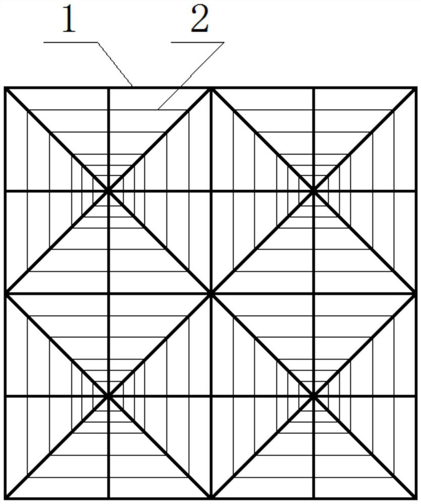
[0055] Such as figure 1 As shown, the present embodiment provides a kind of biofiller, comprising:

[0056] A number of film-hanging units are arranged in a matrix between several film-hanging units;

[0057] Each film-hanging unit includes several skeletons 1 and film-hanging meshes 2, the several skeletons 1 intersect to form the center of each film-hanging unit, and the film-hanging meshes 2 are distributed from dense to sparse from the center to the surrounding On the skeleton 1, each hanging film unit forms a spider web structure.

[0058] The film-hanging meshes 2 of the film-hanging unit in this embodiment are arranged in a multi-circle regular quadrilateral arrangement.

[0059] The skeleton 1 in this embodiment is made of nylon material; the film-hanging mesh 2 is made of vinylon material with good hydrophilicity.

[0060] The biofiller in this example is made into a filler with a planar two-dimensional structure using conventional textile machinery.

Embodiment 2

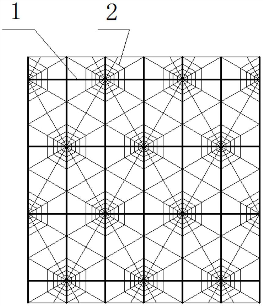
[0062] Such as figure 2 As shown, the difference between the biological filler provided in this embodiment and that of Example 1 is:

[0063] The film-hanging meshes 2 of the film-hanging unit in this embodiment are arranged in a multi-circle regular hexagonal arrangement.

[0064] Skeleton 1 adopts polyester material.

Embodiment 3

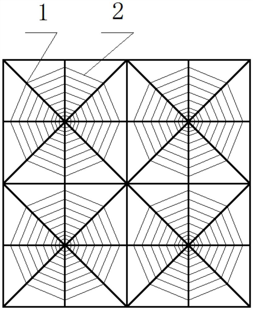
[0066] Such as image 3 As shown, the difference between the biological filler provided in this embodiment and that of Example 1 is:

[0067] The film-hanging meshes 2 of the film-hanging unit in this embodiment are arranged in a multi-circle regular octagonal arrangement.

[0068] Skeleton 1 adopts polyester material.


PUM


Abstract

A biological filler and its installation structure and method, wherein the biological filler includes: several membrane-hanging units arranged in a matrix; each membrane-hanging unit includes several skeletons and membrane-hanging meshes, and the several skeletons The cross forms the center of each membrane-hanging unit, and the membrane-hanging mesh threads are distributed on the skeleton from the center to the surroundings from dense to sparse, so that each membrane-hanging unit forms a spider web structure. The present invention also provides the installation structure and installation method of the above biological filler. The bionic filler in the present invention adopts a bionic spider web structure, which has the advantages of low material consumption, orderly density, fast growth of biofilm, and large amount of bio-adhesion, etc., and can be produced by textile methods, which can reduce production costs , Reduce investment; the installation structure of this kind of biological filler is simple, the installation method is convenient and quick, can ensure the spatial stability of the filler, can capture pollutants in water to a greater extent, and achieve higher sewage treatment efficiency.

Description

technical field [0001] The invention relates to a biological filler and its installation structure and method, in particular to a kind of fabric that can be produced mechanically and rapidly, adopts a bionic spider web structure, and has the advantages of low material consumption, orderly density and order, fast growth of biofilm hanging film, and bioadhesive The invention relates to a biological filler with the characteristics of large quantity and its installation structure and method, which belong to the technical field of water treatment, and in particular relate to a biological sewage / wastewater treatment system. Background technique [0002] At present, there are many biological treatment technologies for sewage / wastewater, and the biological treatment methods are divided into: the treatment method of adding fillers and the treatment method of not adding fillers; comparing the two, the sludge growth environment of the system with fillers is relatively relatively Fixed,...

Claims


Application Information

Patent Timeline
Patent Type & Authority Patents(China)
IPC IPC(8): C02F3/10C02F3/28C02F3/30
CPCC02F3/10C02F3/101C02F3/109C02F3/28C02F3/30Y02W10/10
Inventor 于容朴姚杰宇
Owner 北京华夏大禹科技有限公司
Learn More