Double narrow ring plate-frp joint of thin-walled steel pipe recycled mixed columns and steel beams

A thin-walled steel pipe and mixed column technology, applied in construction, building structure and other directions, can solve the problems of unfavorable waste concrete placement, small steel pipe wall thickness, etc., and achieve the effects of saving manpower, saving steel consumption, and efficient recycling.

Active Publication Date: 2019-01-18
SOUTH CHINA UNIV OF TECH
View PDF8 Cites 0 Cited by
  • Summary
  • Abstract
  • Description
  • Claims
  • Application Information

AI Technical Summary

Problems solved by technology

Commonly used concrete-filled steel tube beam-column joints include: reinforced ring joints, load-bearing pin joints, anchor joints, reinforced concrete ring beam joints, steel bar-through joints, etc. The core component will not be conducive to the placement of waste concrete, and because the wall thickness of the steel tube is small, the use of ordinary ring-type reinforcement components will cause the thin-walled steel tube to buckle prematurely when it is stressed

Method used


Image

  • Double narrow ring plate-frp joint of thin-walled steel pipe recycled mixed columns and steel beams
  • Double narrow ring plate-frp joint of thin-walled steel pipe recycled mixed columns and steel beams
  • Double narrow ring plate-frp joint of thin-walled steel pipe recycled mixed columns and steel beams

Examples


Embodiment Construction

[0027] The present invention will be described in further detail below in conjunction with embodiment and accompanying drawing, but implementation of the present invention

[0028] The method is not limited thereto, and it should be pointed out that, if there are any processes not specifically described in detail below, those skilled in the art can refer to the prior art to implement.

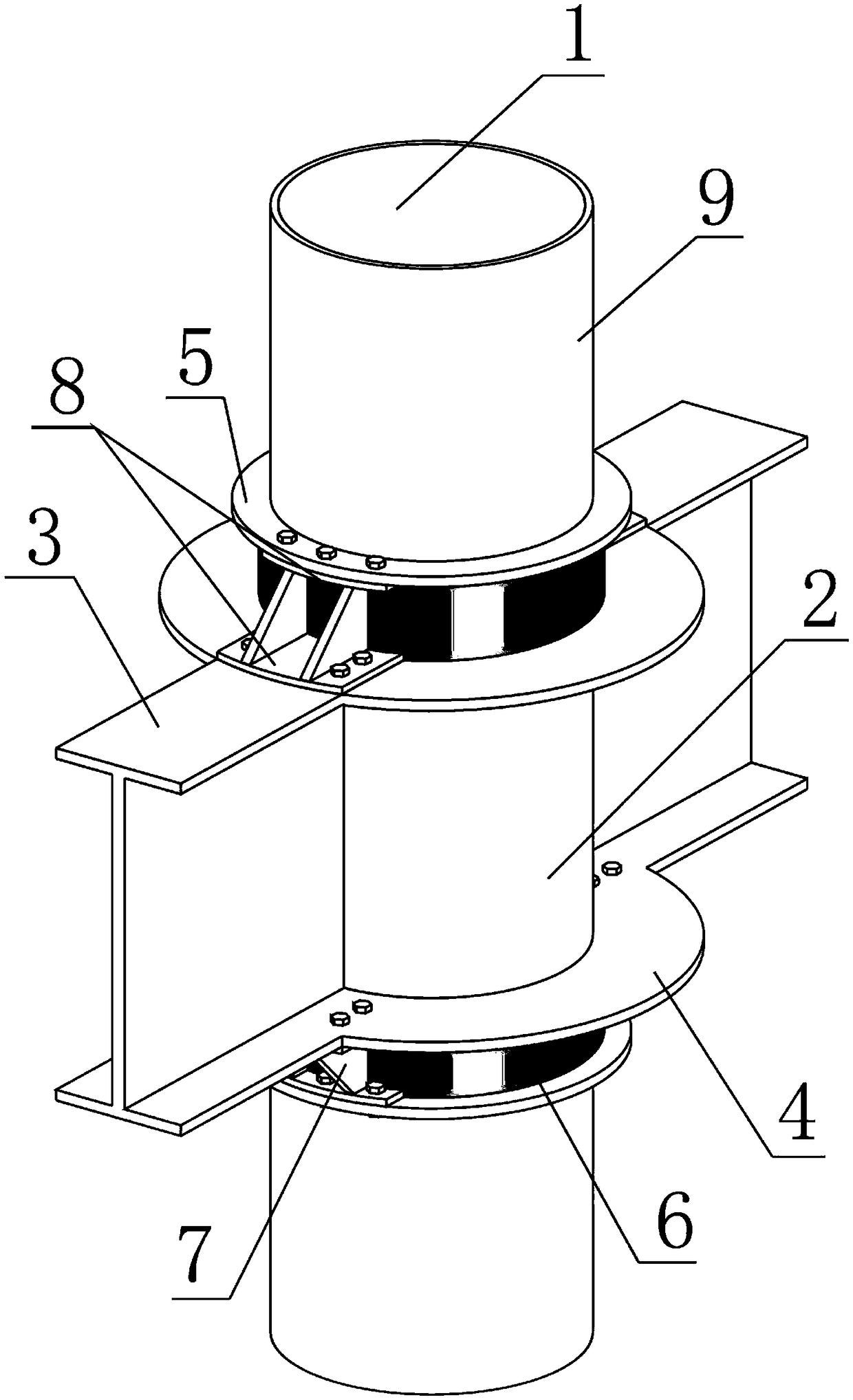
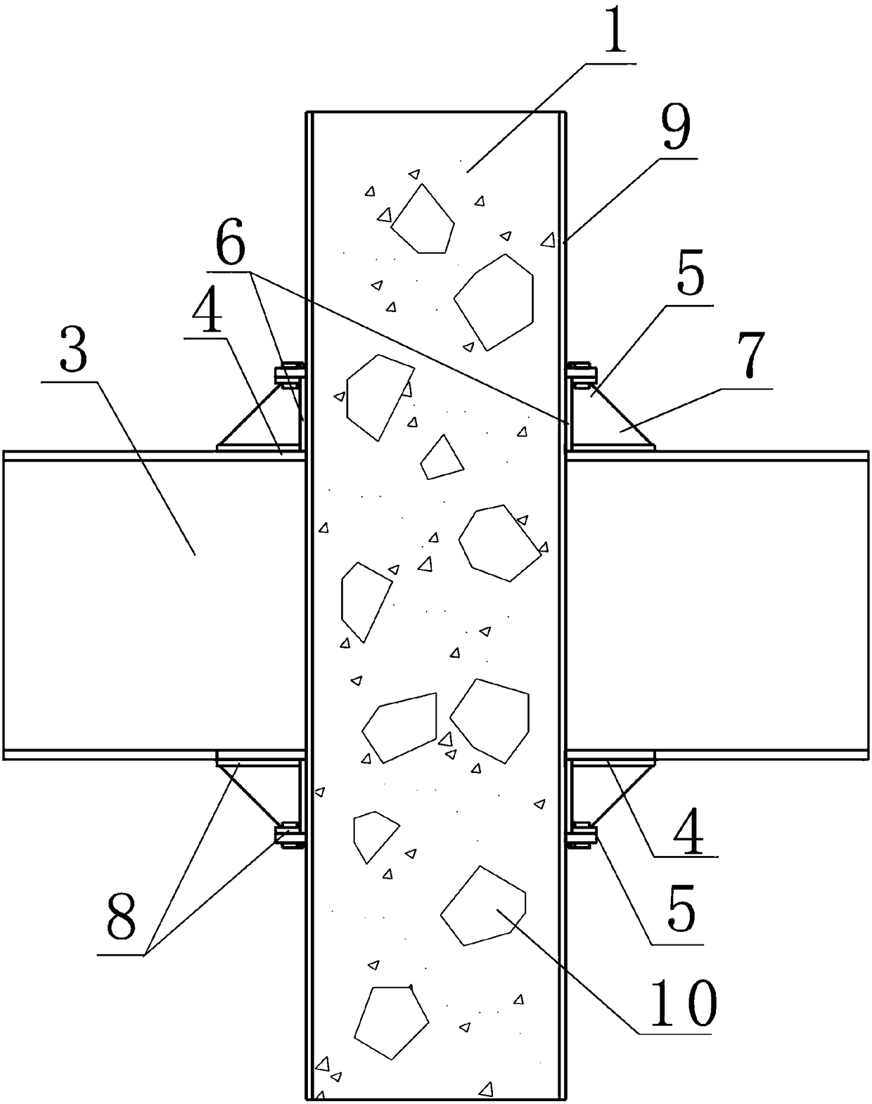
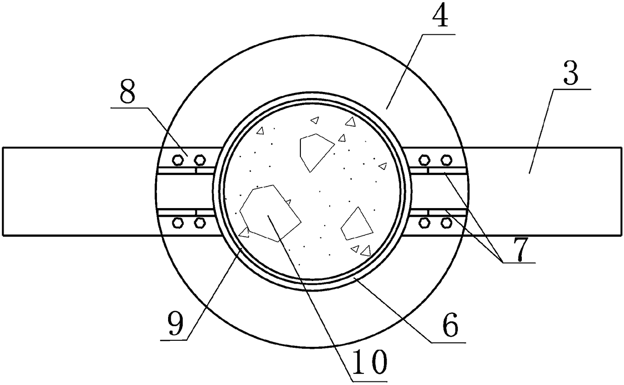
[0029] like Figure 1 to Figure 3 As shown, a double-layer narrow ring plate-FRP joint of thin-walled steel pipe recycled mixed column and steel beam includes a node domain 2 formed by the intersection of thin-walled steel pipe recycled mixed column 1 and steel beam, which is symmetrically arranged on the Two sets of double-layer narrow ring plates on the upper and lower sides of the node domain 2, FRP hoops 6 and composite ribs, steel corbels 3 symmetrically arranged on the left and right sides of the node domain 2, and the steel beams pass through the steel corbels 3 is connected to the node...


PUM

PropertyMeasurementUnit
thicknessaaaaaaaaaa

Abstract

The invention discloses a double-layered narrow annular plate-FRP joint of a thin-walled steel tube regeneration mixing column and a steel beam. The double-layered narrow annular plate-FRP joint of the thin-walled steel tube regeneration mixing column and the steel beam comprises a joint region formed at a junction of the thin-walled steel tube regeneration mixing column and the steel beam, two double-layered narrow annular plates, two FRP hoops and two bracket floors are symmetrically arranged on steel corbels on the left side and the right side of the joint region, the steel beam is connected with the joint region and the double-layered narrow annular plates through the steel corbels, each double-layered narrow annular plate comprises a large annular plate body and a small annular plate body which are parallel to each other, the two double-layered narrow annular plates are positioned on outer side of the thin-walled steel tube on the upper side and the lower side of the joint region respectively, each FRP hoop is adhered to the outer side of the thin-walled steel tube between the corresponding large annular plate body and the corresponding small annular plate body in a surrounding manner, and each bracket floor is symmetrically connected between the large annular plate body and the small annular plate body of the corresponding double-layered narrow annular plate through bolts and tightly presses the corresponding FRP hoop. The double-layered narrow annular plate-FRP joint of the thin-walled steel tube regeneration mixing column and the steel beam is simple in construction and reliable in force transferring; on one hand, the double-layered narrow annular plate-FRP joint is energy-saving and environmentally friendly, and on the other hand, early buckling of the thin-walled steel tube of the joint region when the thin-walled steel tube is stressed is controlled by the double-layered narrow annular plates and the FRP hoops.

Description

technical field [0001] The invention relates to the technical field of waste concrete recycling, in particular to a double-layer narrow ring plate-FRP joint of a thin-walled steel pipe recycled mixed column and a steel beam. Background technique [0002] At present, most of the concrete solid waste generated by the demolition of old buildings in my country is directly transported to the suburbs for stacking, while the concrete needed for new buildings is completely made of new cement, gravel, river sand and other materials. This not only consumes a lot of resources, but also causes serious environmental hazards. For this reason, how to scientifically use the concrete solid waste generated by the demolition of old buildings to minimize the consumption of new cement, gravel, river sand and other materials in new buildings has become a key issue for the entire construction industry to practice "environmental protection, energy saving, and emission reduction". Issues to be reso...

Claims


Application Information

Patent Timeline
Patent Type & Authority Patents(China)
IPC IPC(8): E04B1/58
CPCE04B1/5812E04B1/5837E04B2001/5875
Inventor 赵新宇吴波李卫峰简思敏
Owner SOUTH CHINA UNIV OF TECH
Why Eureka
Try Eureka