
Oil damping mechanism of buffer device

A buffer device and damping mechanism technology, applied in aircraft parts, mechanical equipment, transportation and packaging, etc., can solve problems such as unstable oil hole flow coefficient, loss of landing gear, reduced service life of oil needle, etc., and achieve stable flow coefficient , improve the service life and ensure the stability

Active Publication Date: 2016-11-16
LANDING GEAR ADVANCED MFG
View PDF7 Cites 1 Cited by
  • Summary
  • Abstract
  • Description
  • Claims
  • Application Information

AI Technical Summary

Problems solved by technology

[0003] However, the area of ​​the main oil hole formed by the above-mentioned oil damping mechanism composed of the fixed section oil needle and the fixed oil hole retaining ring is constant during use, and the flow coefficient of the oil hole is unstable as the load gradually increases.
The oil damping mechanism composed of the round platform oil needle and the fixed oil hole retaining ring may greatly reduce the service life of the oil needle due to the irregular impact of the oil during use. Once the oil needle breaks, the landing gear will lose its function when the aircraft lands. Unbelievable

Method used


Image

  • Oil damping mechanism of buffer device
  • Oil damping mechanism of buffer device
  • Oil damping mechanism of buffer device

Examples


Embodiment Construction

[0025] The present invention will be described in detail below with reference to the accompanying drawings and examples. It should be noted that, in the case of no conflict, the embodiments of the present invention and the features in the embodiments can be combined with each other. For the convenience of description, if the words "up", "down", "left" and "right" appear in the following, it only means that the directions of up, down, left and right are consistent with the drawings themselves, and do not limit the structure.

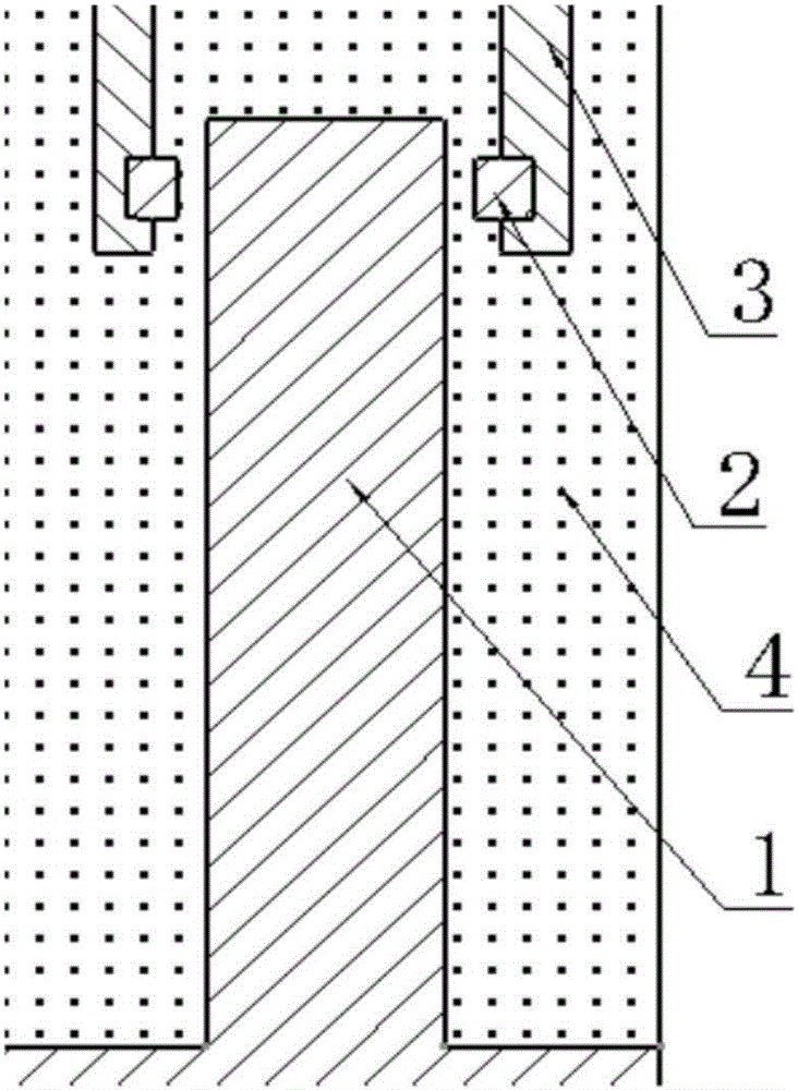
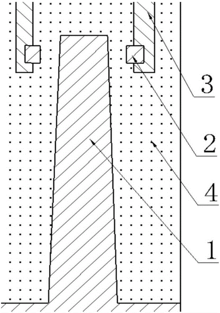
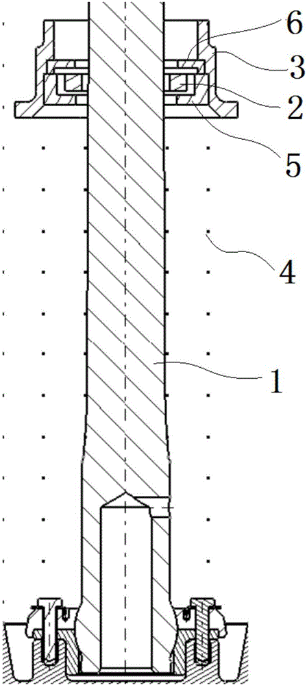
[0026] An oil damping mechanism of a buffer device, see attached image 3 , Figure 4 , a new type of oil damping mechanism, which is a mechanism composed of a rounded square oil needle with variable cross-section and a floating oil hole retaining ring. The main body of the oil needle is a solid body formed by a rounded square multi-section. spherical structure. The oil hole retaining ring can move in multiple degrees of freedom in the buffer device. ...


PUM


Abstract

The invention discloses an oil damping mechanism of a buffer device. The oil damping mechanism of the buffer device comprises an oil needle and an oil hole baffle ring; the oil needle includes a variable-section structured main body with small top and large bottom, and a spherical surface structured bottom; the cross section, perpendicular to the length direction of the oil needle, of the variable section structure is a section formed by smoothing a polygon, and arc lines of all circular angle sections of one section extend to form a circle; and the oil hole baffle ring is in clearance fit with the upper part of the oil needle. The oil damping mechanism of the buffer device is stable in main oil hole flow coefficient in the use process, guarantees stability in the aircraft landing process, and improves comfort in the landing process.

Description

technical field [0001] The invention relates to an oil damping mechanism of a buffer device, which belongs to the field of aircraft system structure design. Background technique [0002] At present, the landing gear buffer device of large and medium-sized transport aircraft generally adopts a fixed section oil needle or a circular platform type oil needle, and the oil hole retaining ring is a fixed structure. For example, Chinese patent CN201010586712.8 discloses a potential energy storage type protrusion landing gear The buffer is an aircraft landing gear buffer. Including outer cylinder, piston rod, central oil hole supporter, pressure rod and limit device. A control cavity is formed between the above-mentioned intermediate support surface and the top of the outer cylinder; a low-pressure air chamber is formed between the top of the oil liquid and the intermediate support surface; the interior and upper part of the piston rod outer cylinder located on the upper part of th...

Claims


Application Information

Patent Timeline
Patent Type & Authority Applications(China)
IPC IPC(8): F16F9/34B64C25/60
CPCB64C25/60F16F9/34
Inventor 张成亮王慧锋黄海清金军慕建全宁晓东折世强傅碧华
Owner LANDING GEAR ADVANCED MFG
Features
  • Generate Ideas
  • Intellectual Property
  • Life Sciences
  • Materials
  • Tech Scout
  • Unparalleled Data Quality
  • Higher Quality Content
  • 60% Fewer Hallucinations
Learn More