
Air source energy tower system with secondary refrigerant centralized control device

A technology of centralized control device and energy tower, applied in air-conditioning systems, heating and ventilation control systems, heating and ventilation safety systems, etc., can solve the problems of difficult manual maintenance, poor automation, and high installation costs, and achieve outstanding substantive characteristics. , Reduce the overflow pipeline and water supply pipeline, and solve the effect of overflow

Inactive Publication Date: 2016-11-16
烟台蓝德空调工业有限责任公司
View PDF6 Cites 0 Cited by
  • Summary
  • Abstract
  • Description
  • Claims
  • Application Information

AI Technical Summary

Problems solved by technology

[0012] The purpose of the present invention is to overcome the deficiencies of the above-mentioned prior art, and provide an air source energy tower system with a refrigerant centralized control device; mainly to solve the existing air source energy tower heat pump system design complex, high installation cost, automatic Poor level, difficult manual maintenance, etc.

Method used


Image

  • Air source energy tower system with secondary refrigerant centralized control device
  • Air source energy tower system with secondary refrigerant centralized control device

Examples


Embodiment 1

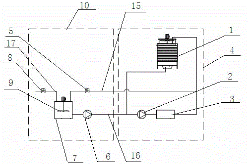
[0020] Example 1, see figure 1 , on the basis of the existing air source energy tower heat pump air conditioner 4, a refrigerant centralized control device 10 is added; the air source energy tower heat pump air conditioner 4 is composed of an energy tower 1, a refrigerant circulation pump 2 and an energy tower heat pump unit 3; The liquid outlet pipeline of the tower 1 is connected to the heat exchanger of the energy tower heat pump unit 3 through the carrier refrigerant circulating pump 2, and then to the liquid inlet pipeline of the energy tower 1, and circulates; The medicine box 7 has an inlet and an outlet on the medicine box 7. The inlet passes through the first pipeline 15 of the first valve 5, and the outlet passes through the second pipeline 16 of the rehydration pump 6, which is connected with the circulation pipe of the air source energy tower heat pump air conditioner 4. The first pipeline 15, the second pipeline 16, and the connection position of the air source en...

Embodiment 2

[0021] Example 2, see figure 1 , with the embodiment 1, the difference is that the rehydration pipeline 17 is installed on the dosing tank 7, and the rehydration pipeline 17 is connected with the tap water or the solution tank through the second valve 8; 9.

Embodiment 3

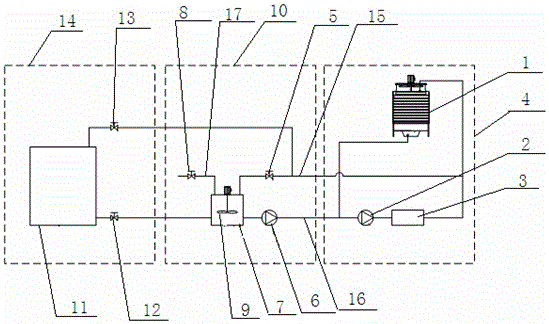
[0022] Example 3, see figure 2 , same as Embodiment 1, the difference is that in the area with high humidity, when the volume of the dosing box 7 is insufficient, a liquid collecting device 14 is installed outside the dosing box 7, and the inlet of the liquid collecting box 11 of the liquid collecting device 14 passes through the first The pipeline of the three valves 13 is connected to the first pipeline 15 or the dosing box 7 , and the outlet of the liquid collecting tank 11 is connected to the dosing box 7 or the infusion pump 6 through the pipeline of the fourth valve 12 .


PUM


Abstract

The invention discloses an air source energy tower system with a secondary refrigerant centralized control device. The air source energy tower system comprises an air source energy tower heat pump air conditioner (4). The air source energy tower heat pump air conditioner (4) is composed of an energy tower (1), a secondary refrigerant circulation pump (2) and an energy tower heat pump unit (3). The system is characterized in that the secondary refrigerant centralized control device (10) is arranged outside the air source energy tower heat pump air conditioner (4), a dosing tank (7) of the secondary refrigerant centralized control device (10) is provided with an inlet and an outlet which are connected with a circulation pipeline of the air source energy tower heat pump air conditioner (4) through pipelines respectively, the energy tower (1) and the dosing tank (7) are each provided with a liquid level sensor, and valves and a fluid supplementing pump (6) are connected with a controller trough circuits. The system has the functions of automatic water supplementation, fluid supplementation and fluid collection, automatic drug feeding and concentration, automatic adjustment for the secondary refrigerant liquid level and concentration and the like, the functions are integrated to be achieved, the design is standardized, connectors are simple, installation is easy, the automatic degree is high, and use is convenient.

Description

Technical field: [0001] The invention relates to the technical field of air-conditioning engineering automatic control, in particular to an air source energy tower system with a carrier refrigerant centralized control device; in particular to the liquid level and concentration of a carrier refrigerant solution in the application process of an air source energy tower heat pump Automatic detection and control system. Background technique: [0002] At present, air-cooled heat pumps and ground source heat pumps are mainly used in heat pump air conditioning systems for heating buildings. The use of air-cooled heat pumps has problems such as frost in winter, low operating efficiency, poor heating effect, and small heating area; the use of ground source heat pumps requires drilling wells, laying and burying pipes, and relying on groundwater. Due to geographical conditions, the construction is inconvenient, and the efficiency is low. [0003] The air source energy tower heat pump s...

Claims


Application Information

Patent Timeline
Patent Type & Authority Applications(China)
IPC IPC(8): F24F5/00F24F11/00
CPCF24F5/0046
Inventor 孟庆山马宾孙洪利张战冯海
Owner 烟台蓝德空调工业有限责任公司
Learn More