
Quick testing equipment

A detection equipment and fast technology, which is applied in the direction of measuring devices, instruments, and optical devices, can solve the problems such as difficulty in guaranteeing imaging clarity, achieve the effects of improving clarity, solving errors, and improving work efficiency

Inactive Publication Date: 2016-11-16
SHENZHEN POLYTECHNIC
View PDF4 Cites 1 Cited by
  • Summary
  • Abstract
  • Description
  • Claims
  • Application Information

AI Technical Summary

Problems solved by technology

[0002] With the development of my country's industry, in the field of industrial production, it is necessary to provide fast and efficient detection methods for industrial products, especially in the fields of profile production and sheet metal processing. By measuring the contours of these products, the contour data obtained by measurement can be used for Further calculate the size of the contour, the graphics formed by the contour shape, etc., such as measuring the vertical section of the profile or the plane profile of the sheet metal, etc., to complete the detection of parameters such as size and position, so that the produced profile or Whether the sheet metal parts meet the design requirements, and at the same time, whether there is a large error in the sectional surface of the measured profile is also an important basis for judging whether the extrusion abrasive is worn and whether the parameters of the feeder are normal. At present, most detection devices use Most of the photos are collected by ordinary cameras, and the clarity of the imaging is difficult to guarantee

Method used


Image

  • Quick testing equipment
  • Quick testing equipment

Examples


Embodiment Construction

[0014] The following will clearly and completely describe the technical solutions in the embodiments of the present invention with reference to the accompanying drawings in the embodiments of the present invention. Obviously, the described embodiments are only some, not all, embodiments of the present invention. Based on the embodiments of the present invention, all other embodiments obtained by persons of ordinary skill in the art without making creative efforts belong to the protection scope of the present invention.

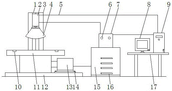
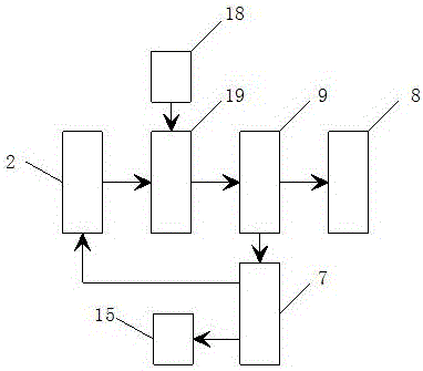
[0015] see figure 1 and figure 2 , an embodiment provided by the present invention: a rapid detection device, including a CCD 2 and a workbench 11, a column 3 is installed above the workbench 11, and the column 3 is provided with a mounting groove 1, a CCD 2 and a ring-shaped LED light source 4 is fixed on the column 3 through the installation groove 1, and the CCD 2 is installed above the ring-shaped LED light source 4, and the CCD 2 is respectively connect...


PUM


Abstract

The invention discloses quick testing equipment which comprises a CCD and a worktable. A vertical column is arranged above the worktable. Furthermore the vertical column is provided with a mounting trough. The CCD and an annular LED light source are fixed on the vertical column through the mounting trough. Furthermore the CCD is mounted above the annular LED light source. The CCD is connected with a circuit controller and a host computer through transmission leads. A working state indicating lamp is arranged at the front surface of the circuit controller. The left side of the host computer is provided with a display device. A driving control device is mounted below the circuit controller. The driving controller is connected with a motor through a transmission lead. The CCD is connected with the host computer through an image collecting unit. The host computer is connected with the driving control device through the circuit controller. Furthermore the output end of the host computer is electrically connected with the input end of the display device. Feedback contrast control technology is utilized in the quick testing equipment, so that higher accuracy of the testing result is realized and a problem of easy errors in testing is settled.

Description

technical field [0001] The invention relates to the technical field of detection equipment, in particular to a rapid detection equipment. Background technique [0002] With the development of my country's industry, in the field of industrial production, it is necessary to provide fast and efficient detection methods for industrial products, especially in the fields of profile production and sheet metal processing. By measuring the contours of these products, the contour data obtained by measurement can be used for Further calculate the size of the contour, the graphics formed by the contour shape, etc., such as measuring the vertical section of the profile or the plane profile of the sheet metal, etc., to complete the detection of parameters such as size and position, so that the produced profile or Whether the sheet metal parts meet the design requirements, and at the same time, whether there is a large error in the sectional surface of the measured profile is also an importa...

Claims


Application Information

Patent Timeline
IPC IPC(8): G01B11/00
CPCG01B11/00
Inventor 朱毅
Owner SHENZHEN POLYTECHNIC
Learn More